In modern automation and security systems, laser sensor switches are indispensable components. They offer high precision, reliability, and non-contact detection, making them ideal for applications ranging from industrial machinery safety gates to sophisticated home security setups. However, their effectiveness hinges entirely on correct installation and wiring. A miswired sensor can lead to system failure, false triggers, or even damage to the device. This guide provides a clear, step-by-step walkthrough on how to wire a common type of laser sensor switch, complete with explanatory diagrams to ensure you get it right the first time.
Before handling any wires, safety is paramount. Always disconnect power from the main circuit before beginning any electrical work. Verify the voltage rating of your laser sensor switch (commonly 12-24V DC or 110-240V AC) and ensure your power supply matches. Have your tools ready: wire strippers, screwdrivers, and possibly a multimeter for testing. Most importantly, consult the specific datasheet provided by the manufacturer of your sensor model, as pin configurations and functions can vary.
A typical laser sensor switch system consists of two main units: the Transmitter (Tx) and the Receiver (Rx). The Transmitter emits a focused laser beam. The Receiver detects this beam. When an object interrupts the beam, the Receiver's output state changes, sending a signal to a controller like a PLC, relay, or alarm system.
Let's break down the wiring for a standard 3-wire DC sensor (NPN or PNP output type are most common). These wires are usually color-coded: Brown for positive voltage supply (+V), Blue for common negative or ground (0V), and Black for the output signal (OUT).
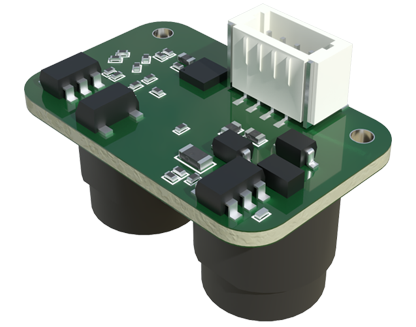
Wiring Diagram & Procedure:

1. Power Supply Connections:
* Connect the Brown wire from both the Transmitter and the Receiver to the positive terminal (+V) of your DC power supply (e.g., 12V or 24V).
* Connect the Blue wire from both the Transmitter and the Receiver to the negative or ground terminal (0V/COM) of the same DC power supply.
* This provides operating power to both units. Ensure the beam from the Transmitter is accurately aligned with the lens of the Receiver. Many units have alignment indicators (like LEDs) that show optimal beam reception.
2. Output Signal Connection:
* The Black wire from the Receiver is the critical output signal wire. Its function depends on whether you have an NPN (sinking) or PNP (sourcing) sensor.
* For an NPN Sensor: The Black wire acts as a switched negative. When the beam is uninterrupted (normal state), the output is "off" (high impedance). When the beam is broken, the Black wire connects internally to 0V (Blue wire). You would wire this Black wire to one terminal of your load (e.g., a PLC input, relay coil). The other terminal of the load is connected to the positive supply (+V). Thus, when the beam breaks, current flows from +V, through the load, into the Black wire, and to ground, activating the load.
* For a PNP Sensor: The Black wire acts as a switched positive. When the beam is broken, the Black wire connects internally to +V (Brown wire). Wire the Black wire to one terminal of your load. The other terminal of the load is connected to the ground (0V). Activation provides positive voltage to the load.
3. Connecting to a Controller:
* For connection to a Programmable Logic Controller (PLC), identify a digital input (DI) point. For an NPN sensor, connect the Black wire to the DI point, and that DI point's common is typically connected to +V internally. For a PNP sensor, connect the Black wire to the DI point, and the DI common is connected to 0V. Always check your PLC manual.
4. Testing and Troubleshooting:
* After connections are secure, restore power. Most sensors have a power-on LED. Carefully break the laser beam (use an opaque object). You should see an output LED illuminate on the Receiver and hear your connected load (like a relay) click.
* If the system doesn't work: Double-check all wire connections against the diagram and datasheet. Verify power supply voltage with a multimeter. Ensure the laser beam is perfectly aligned. Check for obstructions and clean the lenses.
For two-wire AC sensors (often used in simple alarm circuits), wiring is more straightforward but handles higher voltage. One wire connects to the Live (Hot) AC source, and the other wire connects to one end of the load (e.g., a siren). The other end of the load connects to the Neutral AC line. The sensor acts as a switch directly in the hot line. Extreme caution is required when working with AC mains voltage.
Proper wiring is the foundation of a robust laser sensor system. By following these principles, referring to the visual diagrams, and always prioritizing the manufacturer's instructions, you can integrate these precise sensors into your projects confidently, ensuring safe and reliable operation for years to come.