In the realm of industrial automation and electronic control, Hall Effect proximity switches stand as a cornerstone technology for non-contact position and speed sensing. Their reliability, solid-state nature, and immunity to environmental contaminants make them a preferred choice over mechanical limit switches in countless applications, from automotive camshaft detection to conveyor belt monitoring. For engineers tasked with selecting, integrating, or troubleshooting these devices, a deep understanding of their key parameters is not just beneficial—it is essential for ensuring optimal system performance, longevity, and safety.
At its core, a Hall Effect sensor operates on the principle discovered by Edwin Hall. When a current-carrying conductor is placed in a magnetic field, a voltage (the Hall voltage) is generated perpendicular to both the current and the field. A proximity switch utilizes this phenomenon. It contains a Hall element, signal conditioning circuitry, and an output stage. When a ferromagnetic target (like a gear tooth or a magnet) approaches the sensor's active face, it alters the magnetic field density, which the Hall element detects. The conditioned signal then triggers the output switch—typically an NPN or PNP transistor—to change state.
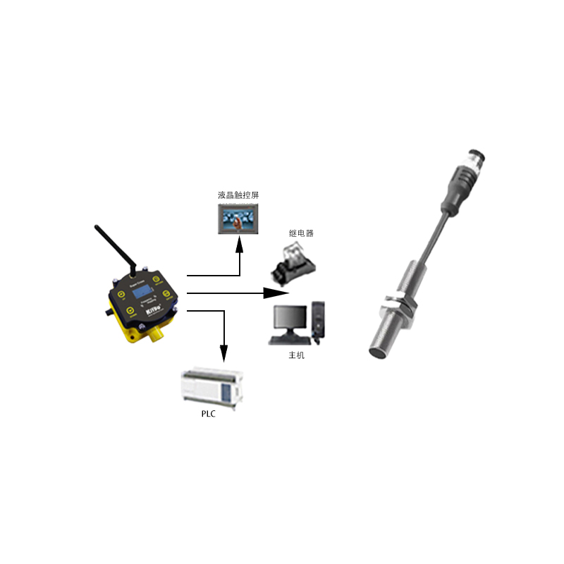
The selection process begins with the Operating Voltage Range. This specifies the DC supply voltage within which the sensor is guaranteed to function correctly. Common ranges are 4.5 to 24 VDC or 10 to 30 VDC. Operating outside this range can lead to erratic behavior or permanent damage. Closely tied to this is the Current Consumption, which indicates the sensor's own power draw, typically in the milliampere range. This is crucial for calculating the total load on the power supply.
The Output Configuration is a critical decision point. The two primary types are NPN (sinking) and PNP (sourcing) outputs. In an NPN configuration, the load is connected between the output terminal and the positive supply; the sensor sinks current to ground when active. In a PNP configuration, the load is connected between the output and ground; the sensor sources current from the positive supply. The choice is dictated by the control system's input card requirements (e.g., PLC inputs). Furthermore, outputs can be Normally Open (NO) or Normally Closed (NC), defining the switch's idle state. Some advanced sensors offer programmable or push-pull outputs for flexibility.
Switching Capacity (Max. Output Current) defines the maximum continuous current the sensor's output transistor can handle, such as 200 mA. Exceeding this value risks overheating and failure. The related Leakage Current specifies the tiny current (microamperes) that may flow through the output in its "off" state. In sensitive circuits, high leakage current can be misinterpreted as an "on" signal, necessitating a pull-down resistor.
Switching Frequency or Max. Response Frequency, measured in Hertz (Hz) or kilohertz (kHz), determines how quickly the sensor can respond to targets. A sensor with a 5 kHz rating can theoretically detect up to 5,000 targets per second. This parameter is vital for high-speed applications like rotary encoders or fast-moving production lines.
Sensing Distance (Sn) is arguably the most referenced specification. It is the nominal or rated operating distance at which the sensor is guaranteed to switch under standardized conditions (voltage, temperature, target material/size). For inductive Hall sensors (reacting to ferrous metals), this is typically a few millimeters. For sensors with an integrated magnet, reacting to a ferrous target, it can be longer. The Hysteresis is the difference between the switch-on point (as the target approaches) and the switch-off point (as it recedes). Expressed as a percentage of the sensing distance, hysteresis prevents output chatter when the target is at the threshold, ensuring a clean, single switching event.
Environmental robustness is defined by several parameters. The Operating Temperature Range (e.g., -25°C to +85°C) specifies the ambient conditions for reliable operation. The Protection Rating, denoted by an IP (Ingress Protection) code (e.g., IP67), indicates the level of protection against solid particles and liquids. An IP67 rating means the sensor is dust-tight and can withstand temporary immersion in water. For harsh environments, resistance to Vibration and Shock is also specified.
Other important considerations include the Short-Circuit Protection and Reverse Polarity Protection features, which safeguard the sensor from common wiring errors. The Output State Indicator (LED) is a practical feature for visual diagnostics during installation and maintenance. Finally, the Electrical Connection style (pre-wired cable, M8/M12 connector) impacts installation time and maintenance ease.
In conclusion, the successful deployment of a Hall