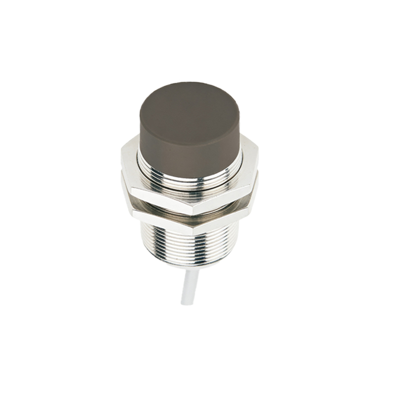
In the realm of industrial automation and control systems, proximity sensors stand as fundamental components for non-contact detection. Their reliability and performance are intrinsically tied to one critical parameter: the power supply voltage. As an electrical engineer, a nuanced understanding of this aspect is not merely beneficial—it is essential for ensuring system integrity, longevity, and safety. This article delves into the intricacies of proximity sensor power supply voltage, covering standard ranges, implications of deviation, selection criteria, and practical considerations.
Proximity sensors, including inductive, capacitive, and photoelectric types, are predominantly designed to operate on Direct Current (DC) power supplies. The most common standardized voltage ranges are 10-30V DC and 20-250V AC/DC for certain robust models. Within the DC domain, 12V DC and 24V DC have emerged as de facto industrial standards. The 24V DC system is particularly prevalent in factory automation due to its superior noise immunity compared to lower voltages. It allows for longer cable runs with minimal voltage drop, a crucial factor in expansive industrial setups. The operating voltage window (e.g., 10-30V DC) is specified to account for typical fluctuations in industrial power networks. Operating a sensor at the nominal voltage (e.g., 24V) within this range ensures optimal performance.
Deviation from the specified voltage range carries significant consequences. Undervoltage is a primary culprit for sensor malfunction. When the supply voltage dips below the minimum threshold (e.g., below 10V for a 10-30V DC sensor), the sensor's internal circuitry may fail to energize properly. This can lead to inconsistent switching behavior, reduced sensing distance, or complete failure to detect targets. In some cases, the sensor might oscillate erratically, sending false signals to the programmable logic controller (PLC) and causing unintended machine behavior or process faults.
Conversely, overvoltage poses a more immediate threat of catastrophic failure. Applying a voltage significantly above the maximum rating can cause irreversible damage to the sensor's electronic components. The most vulnerable point is often the output switching element (transistor). A voltage spike can lead to thermal overstress or dielectric breakdown, resulting in a short-circuit or open-circuit failure. This not only necessitates sensor replacement but can also potentially damage the connected control input module on the PLC, escalating repair costs and downtime. Transient voltage spikes, commonly from inductive load switching (e.g., solenoids, relays) on the same power line, are a frequent source of such overvoltage events.
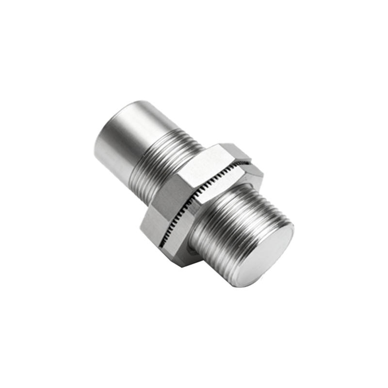
Therefore, selecting the appropriate power supply is a critical design step. A regulated, stabilized DC power supply is highly recommended over an unregulated one. The power supply's current rating must be sufficient to handle the inrush current of all connected sensors and their loads simultaneously. A good practice is to calculate the total load and add a 20-30% safety margin. For installations in electrically noisy environments or with long cable runs, additional protective measures are warranted. These include using shielded cables, proper grounding, and installing protective devices such as surge suppressors or Transient Voltage Suppression (TVS) diodes near the sensor. For sensors with switching outputs, always ensure the load (e.g., a PLC input) is compatible with the sensor's output configuration (PNP or NPN) and voltage level.
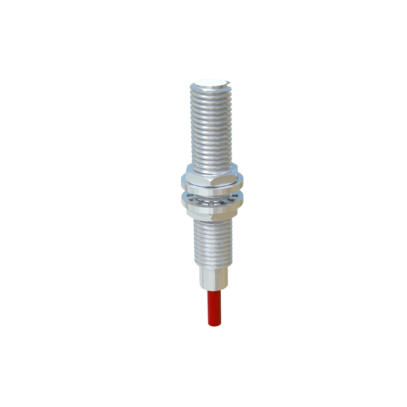
In practice, voltage drop across long wiring is a frequently overlooked issue. Using conductors with insufficient gauge for the required current and distance can result in the sensor receiving a voltage far lower than the source. This is especially critical with 24V systems powering multiple sensors over distance. Engineers must perform voltage drop calculations during the design phase to select adequate wire sizes. Furthermore, when replacing a sensor, verifying the voltage at the sensor's terminals under load, rather than assuming it matches the panel supply voltage, is a vital troubleshooting step.
In conclusion, the power supply voltage is the lifeblood of a proximity sensor. Adherence to manufacturer specifications, careful system design considering the electrical environment, and the implementation of protective strategies are non-negotiable for robust operation. By meticulously managing this parameter, electrical engineers can build control systems that are not only functional but also resilient and reliable, minimizing unscheduled downtime and maximizing productivity in industrial applications. Always consult the specific sensor's datasheet for its absolute maximum ratings and operational guidelines, as these are the ultimate authority for proper integration.