In the realm of industrial automation, precision measurement is paramount. Laser distance sensors have become indispensable tools, offering non-contact, high-accuracy measurement for a vast array of applications, from robotics and logistics to construction and quality control. While the core technology of time-of-flight or phase-shift measurement is well-understood, the user interface—specifically, the sensor display—plays a critical role in effective deployment, configuration, and troubleshooting. This article delves into the intricacies of laser distance sensor displays, exploring their functions, common readouts, and best practices for interpretation.
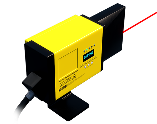
Modern laser distance sensors typically feature one of several display types: simple LED indicators, multi-digit numeric LCD/LED screens, or sophisticated graphical interfaces. The most common in industrial settings is the numeric display, often accompanied by status LEDs. The primary value shown is, of course, the measured distance. However, engineers must be adept at interpreting more than just this number. The unit of measurement (e.g., mm, cm, inches) is usually indicated, either on the display itself or via a configuration setting. A stable reading is ideal, but fluctuations can indicate vibration, target surface inconsistency (e.g., uneven texture, transparency), or environmental interference like dust or strong ambient light.
Beyond the raw distance value, the display is a window into the sensor's operational status. Key indicators often include:
* Signal Strength/Quality: Often represented by bar graphs or specific codes (e.g., "SIG: OK" or "QLT: 75%"). A weak signal may suggest the target is out of range, too reflective (causing saturation), or not reflective enough. It can also be affected by dirty optics.
* Error Codes and Alarms: Displays communicate fault conditions. Common codes might indicate "E-01" for out-of-range, "E-02" for signal loss, or "E-03" for internal error. Referencing the manual is crucial here.
* Configuration Mode Indicators: When programming measurement modes (e.g., continuous measurement, single-shot, window mode for tolerance checking), the display guides the user through menus, showing parameters like measurement rate, output configuration (analog 4-20mA, digital IO, serial communication), and setpoints.
* Output State: For sensors with switching outputs, the display may show the status of each output (e.g., "OUT1: ON") relative to the programmed thresholds.
A critical aspect often displayed is the measurement mode. Sensors might operate in "Reference Mode," where measurements are relative to a user-set zero point (e.g., the sensor housing), or "Absolute Mode," measuring from the sensor's front lens. The display must clearly indicate which mode is active to avoid interpretation errors. Furthermore, advanced sensors with "Teach-In" functionality use the display to confirm the programming of upper and lower limits by simply pointing the laser at the desired boundaries.
For sensors integrated into complex systems via PROFINET, EtherNet/IP, or IO-Link, the local display remains vital for initial setup and diagnostics. It can show the device's network address, communication status, and real-time data before full system integration is complete. This allows for on-the-spot verification without needing a connected HMI or PLC programmer.
Best practices for working with laser sensor displays include:
1. Initial Calibration and Zeroing: Always perform recommended calibration procedures, using the display to confirm the baseline measurement against a known reference.
2. Understanding Environmental Limits: Monitor the signal quality readout when installing the sensor. A consistently low reading in a clean environment may necessitate sensor re-positioning or choosing a different model (e.g., with a stronger laser class or different wavelength).
3. Systematic Troubleshooting: Use the displayed error codes and signal strength as the first diagnostic step before checking wiring or controller logic.
4. Regular Verification: Periodically check the sensor's reading against a physical gauge to detect any drift, which may not be obvious from the display alone but can be inferred from changes in process quality.
In conclusion, the display on a laser distance sensor is far more than a simple number readout. It is an essential diagnostic and configuration tool. A deep understanding of its symbols, codes, and modes empowers engineers to deploy these sensors more reliably, maintain system integrity, and swiftly resolve operational issues, thereby ensuring the continued precision and efficiency of automated processes. Mastery of this interface translates directly to optimized performance and reduced downtime.