Proximity sensors are critical components in industrial automation, robotics, and safety systems, detecting the presence or absence of objects without physical contact. Proper adjustment of their direction is essential for reliable operation, accuracy, and longevity. This guide provides a step-by-step approach to adjusting proximity sensor direction, tailored for engineers and technicians in the electrical and automation fields.
First, understand the sensor type. Inductive sensors detect metallic objects, capacitive sensors handle non-metallic materials, and ultrasonic or photoelectric sensors use sound or light waves. Each type has specific directional characteristics. For instance, inductive sensors typically have a sensing face where the electromagnetic field is strongest, requiring precise alignment toward the target. Review the manufacturer’s datasheet for the sensor’s sensing range, beam angle, and recommended mounting orientation.
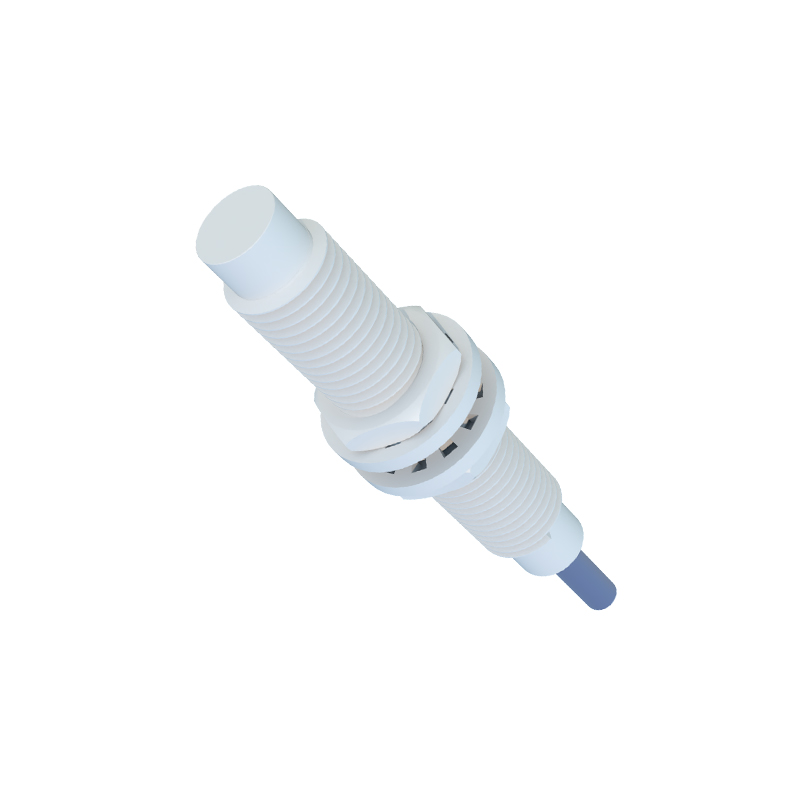
Begin with installation. Mount the sensor securely on a stable surface, ensuring it is aligned parallel to the expected path of the target object. Use adjustable brackets or fixtures if needed, as vibration or misalignment can cause false readings. For cylindrical sensors, note the marked sensing direction on the housing. Adjust the sensor’s angle so that its active surface faces the target directly, minimizing oblique angles that reduce effective sensing distance.
Next, set the sensing distance. Most proximity sensors have a specified nominal range (e.g., 5mm to 20mm). Adjust the distance between the sensor and target within this range, considering factors like target material, size, and speed. For example, with inductive sensors, reduce the distance for smaller metals or increase it for larger objects. Use a gauge or shim to fine-tune the gap, ensuring the target passes consistently through the sensing zone without triggering early or late detection.
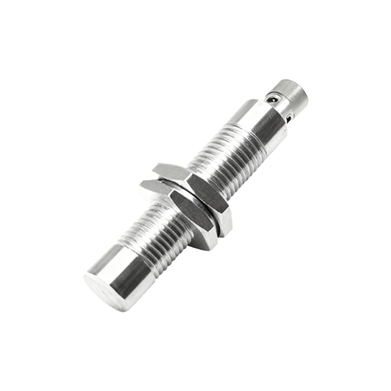
Calibrate the sensor using its adjustment controls. Many sensors feature potentiometers or digital interfaces for sensitivity adjustment. Turn the potentiometer clockwise to increase sensitivity or counterclockwise to decrease it, aiming for a stable detection signal. For directional adjustments, test by moving the target across the sensor’s field. Observe the output indicator (usually an LED) to ensure it activates only when the target is within the desired direction and range. Avoid over-sensitivity, which may pick up interference from nearby objects.
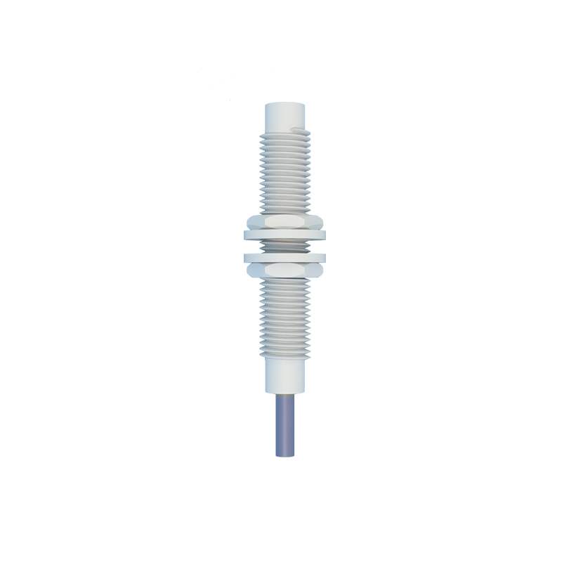
Consider environmental factors. Electrical noise, temperature changes, or nearby machinery can affect directionality. Shield the sensor from electromagnetic interference by using shielded cables and proper grounding. For photoelectric sensors, clean the lens regularly to prevent dust from deflecting the light beam. In applications with multiple sensors, space them adequately to prevent crosstalk, adjusting their directions to avoid overlapping sensing fields.
Test the adjustment under operational conditions. Run the system at normal speed, monitoring the sensor’s response with an oscilloscope or PLC diagnostics. Check for missed detections or false triggers, and readjust the direction if necessary. Document the settings, including angle, distance, and sensitivity, for future maintenance. Regular audits are recommended, as wear or environmental shifts may require readjustment over time.
In summary, adjusting proximity sensor direction involves correct mounting, precise distance setting, careful calibration, and environmental mitigation. By following these steps, engineers can optimize sensor performance, enhancing system reliability and efficiency in automation setups. Always prioritize safety by disconnecting power during adjustments and adhering to industry standards like IEC 60947-5-2.