In the realm of industrial automation and control systems, proximity sensors are indispensable components. A thorough understanding of the main diagram, or schematic, of a proximity sensor is crucial for electrical engineers involved in design, installation, troubleshooting, and maintenance. This guide delves into the core elements of a typical proximity sensor main diagram, explaining its functionality and key components in detail.
At its heart, the main diagram of a proximity sensor illustrates the electrical and functional connections of the device. It serves as a blueprint, detailing how the sensor interfaces with power sources, loads, and control systems. The diagram typically includes the sensor itself, represented by a standardized symbol, and its connection terminals. For a standard 3-wire DC sensor, these terminals are usually labeled as Brown (or +V), Blue (or 0V/Common), and Black (or Signal Output). The diagram clearly shows the power supply connections: the Brown wire connects to the positive DC voltage, and the Blue wire connects to the DC common or ground. The critical output signal is carried by the Black wire.
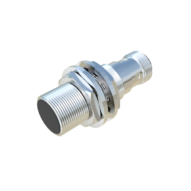
The output configuration is a central part of the diagram. Proximity sensors are primarily categorized as PNP (sourcing) or NPN (sinking) types. In a PNP main diagram, the Black output wire is shown connected internally to the positive supply; when the sensor detects a target, it sources current to the load. Conversely, in an NPN diagram, the Black wire is internally connected to the common/ground; it sinks current from the load upon detection. The diagram will depict the load (e.g., a PLC input module, relay coil, or indicator lamp) connected between the output wire and the opposite power rail. For a PNP sensor, the load connects between the Black wire and the Blue (common). For an NPN sensor, the load connects between the Brown (positive) and the Black wire. This distinction is paramount for correct circuit design and preventing damage.
Furthermore, the diagram often includes protective and functional components. These may be represented by specific symbols. A reverse polarity protection diode is commonly integrated to safeguard the sensor from accidental incorrect power connection. Status indication LEDs are also shown, illustrating their connection to the internal logic to provide visual confirmation of power and output state. Some advanced sensor diagrams include timing functions (like on-delay or off-delay), which are represented by additional logic blocks or symbols within the sensor's boundary.
Wiring considerations are implicitly conveyed through the diagram. It emphasizes the necessity of using shielded cables in electrically noisy environments, with the shield properly grounded at the controller end, not at the sensor. The diagram also underscores the importance of adhering to voltage and current ratings specified for both the power supply and the load. Incorrect loading can lead to sensor failure or unreliable operation.
Interpreting the main diagram is essential for troubleshooting. If a sensor fails to trigger, an engineer would reference the diagram to systematically check: power presence between Brown and Blue, the state of the output signal (Black to Blue for PNP, or Brown to Black for NPN) with and without a target, and the continuity and integrity of all connections as per the schematic. Understanding whether the output should be "high" or "low" during detection is directly derived from the PNP/NPN configuration shown in the diagram.
In conclusion, the main diagram of a proximity sensor is far more than a simple wiring chart. It is a fundamental document that encapsulates the sensor's electrical soul—its power requirements, output logic, internal protections, and interface methodology. Mastery of this diagram enables electrical engineers to seamlessly integrate these sensors into complex control systems, ensure robust and reliable operation, and swiftly resolve any operational issues that may arise. Always consult the specific manufacturer's datasheet and diagram for the exact specifications and connection details of the sensor model in use.