In industrial automation and motion control systems, accurate rotational speed measurement is paramount for process efficiency, equipment safety, and predictive maintenance. Proximity sensors, particularly inductive and capacitive types, are widely employed for this purpose due to their non-contact operation, robustness, and relatively simple integration. However, inherent and application-specific errors can significantly impact the accuracy of speed readings derived from these sensors. Understanding the sources of these errors and implementing effective mitigation strategies is crucial for system engineers.
The fundamental principle involves the sensor detecting a passing metallic or dielectric target (e.g., a gear tooth, keyway, or bolt head) on a rotating shaft. The sensor generates a pulse for each target passage. Rotational speed (RPM) is calculated based on the frequency of these pulses and the known number of targets per revolution. The primary error sources can be categorized into sensor-related, target-related, installation-related, and signal processing-related factors.
Sensor-Related Errors:
1. Response Time & Switching Frequency: Every sensor has a maximum switching frequency. If the pulse frequency exceeds this limit, the sensor cannot reliably detect every target, leading to missed counts and a lower-than-actual speed reading. This is critical for high-speed applications.
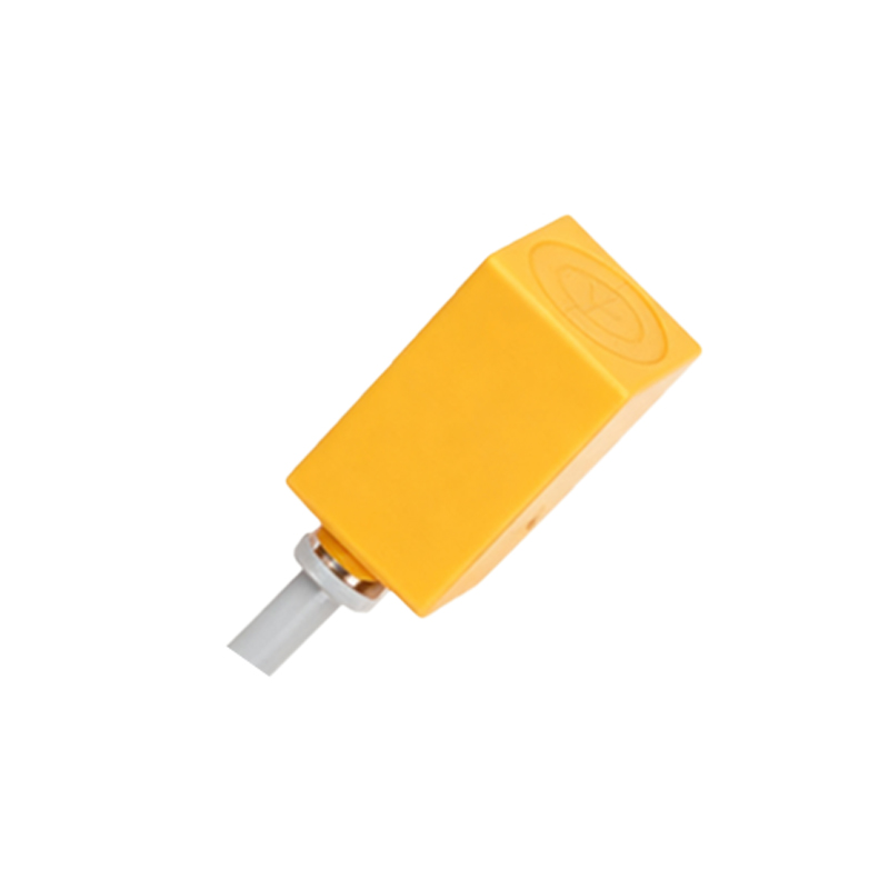
2. Hysteresis: The difference between the switch-on and switch-off points can cause timing jitter in the output signal, especially if the target speed or vibration levels are variable. This jitter translates directly into speed calculation error.
3. Temperature Drift: Changes in ambient temperature can affect the oscillator circuit in inductive sensors, slightly altering the nominal sensing distance and potentially causing inconsistent detection.
Target-Related Errors:

1. Target Geometry and Consistency: Variations in target size, shape, or profile (e.g., worn or uneven gear teeth) cause fluctuations in the point of detection. This results in pulse width modulation and period inconsistency, introducing significant error in instantaneous speed calculations.
2. Target Material: For inductive sensors, the material's conductivity and permeability affect the sensing distance and signal strength. Mixed or inconsistent materials can lead to detection variability.
3. Eccentricity and Runout: If the target pattern is not perfectly concentric with the shaft's axis of rotation, the distance between the sensor and target varies periodically. This creates a cyclic error in the pulse timing.
Installation-Related Errors:
1. Air Gap Variance: The distance between the sensor face and the target is critical. Excessive, insufficient, or varying air gap can lead to unreliable switching or missed detections. Mechanical vibration or bearing wear can dynamically alter this gap.
2. Misalignment: Angular misalignment between the sensor axis and the target surface can reduce effective signal strength and cause inconsistent triggering.
3. Environmental Interference: Electromagnetic interference (EMI) from nearby motors, drives, or power lines can induce noise in the sensor signal or its cabling, causing false triggers or signal degradation.
Signal Processing & Measurement Errors:
1. Timer/Counter Resolution: The digital system (PLC, microcontroller) measuring the time between pulses has a finite resolution. At very high speeds (short periods), this quantization error becomes a substantial percentage of the measurement.
2. Algorithm Choice: The method of calculating RPM (e.g., measuring the period between two pulses vs. counting pulses over a fixed time window) has different error characteristics. Period measurement is sensitive to jitter on a single pulse, while frequency averaging over a window introduces latency and can smooth out important transient variations.
3. Debounce Filtering: Improperly configured digital debounce filters can distort the pulse waveform, effectively shifting the detected edge in time.
Mitigation Strategies for Improved Accuracy:
Sensor Selection: Choose a sensor with a switching frequency significantly higher than the maximum expected pulse frequency. Consider sensors with minimal hysteresis and high temperature stability for critical applications.
Target Design: Use multiple, identical, and precisely machined targets per revolution to increase the pulse count, which improves resolution and can average out some geometric errors. Ensure targets are mounted with minimal runout.
Precision Installation: Adhere strictly to the recommended air gap. Use mounting fixtures to ensure stability and alignment. Employ vibration-damping mounts if necessary.
Shielding and Filtering: Use shielded cables, proper grounding techniques, and ferrite cores to suppress EMI. Implement analog filtering at the signal source before digital conversion where appropriate.
Advanced Signal Processing: Utilize high-resolution timers/counters. Implement adaptive algorithms; for instance, use a hybrid method that calculates speed from the average period of multiple pulses (e.g., M method) to reduce the impact of edge jitter. For highly dynamic systems, consider Kalman filtering to fuse sensor data with a system model.
Regular Cal