Photoelectric proximity sensors are indispensable components in modern industrial automation, offering non-contact detection of objects based on the modulation of light. Their adjustment is critical for ensuring reliable operation in diverse environments. Understanding the core principles behind these adjustments requires a grasp of the sensor's fundamental operation, which typically involves an emitter (light source) and a receiver (photodetector). The primary adjustment parameters include sensitivity, response time, and, for some models, the light beam characteristics.
The most common adjustment is sensitivity or threshold setting. This determines the minimum amount of light change the receiver must detect to trigger an output signal. In a through-beam sensor, where emitter and receiver are separate, sensitivity adjustment compensates for gradual lens contamination or minor misalignment. For diffuse-reflective sensors, which detect light reflected from the target, sensitivity adjustment is paramount. It must be finely tuned to distinguish the target from the background and to account for variations in target color, reflectivity, and surface texture. A target with high reflectivity (like a white surface) will return a strong signal, whereas a dark, matte target will return a weak one. The sensitivity potentiometer or digital setting effectively sets the trigger point on the received light intensity curve. Setting it too high may cause false triggers from ambient light or reflective backgrounds; setting it too low may cause the sensor to miss a low-reflectivity target.
Response time or switching frequency adjustment is another key principle. This defines how quickly the sensor can react to a change in state (object present/absent). In high-speed packaging or sorting lines, a fast response time is essential to maintain precision. However, an excessively fast setting in an electrically noisy environment can make the sensor susceptible to interference, causing erratic switching. Therefore, the adjustment often involves a trade-off between speed and noise immunity. Many sensors feature a selectable response time or incorporate filtering algorithms that can be adjusted to suit the application's speed requirements and environmental conditions.
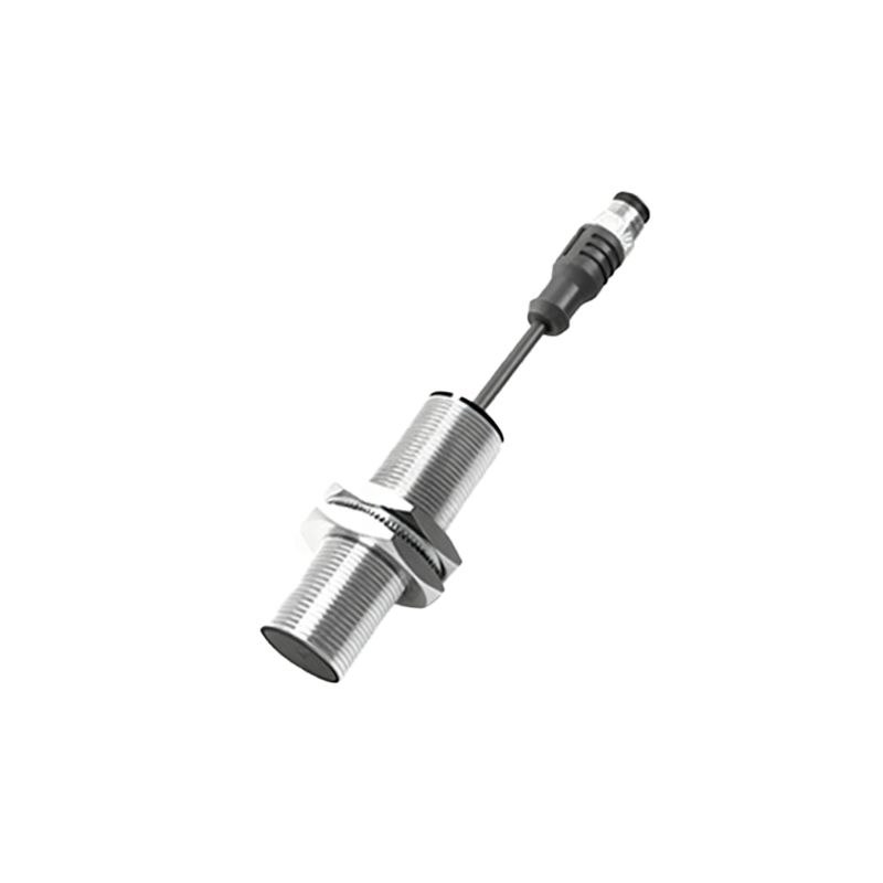
For sensors with a modulated light source (typically pulsed infrared LED), the principle of synchronization or background suppression is crucial. Modulation allows the sensor to ignore constant ambient light (like sunlight or workshop lighting) and only respond to its own pulsed signal. Some advanced diffuse sensors, known as background suppression (BGS) or distance-settable sensors, allow adjustment of the effective sensing range. They work on the triangulation principle, where the position of the reflected light spot on a special receiver array determines the distance. By electronically adjusting the evaluation point on this array, the exact switching point distance can be set, allowing the sensor to ignore objects beyond a certain range, even if they are more reflective.
Alignment is a fundamental adjustment for through-beam and retro-reflective types. Precise mechanical alignment of the emitter and receiver axes ensures maximum light energy transfer. Many housings feature visual indicators (like alignment LEDs) that change state when optimal alignment is achieved. For retro-reflective sensors using a corner-cube reflector, an additional adjustment may be needed to compensate for polarization filters used to avoid false triggers from shiny surfaces.
Environmental compensation is an implicit adjustment principle. Factors like temperature, humidity, and dust affect light transmission. High-quality sensors incorporate circuitry to compensate for gradual LED output decay over time or temperature-induced drift, maintaining a consistent operating point. However, initial setup should always be performed under representative operating conditions.
The adjustment procedure generally follows a logical sequence: First, install the sensor mechanically. Second, perform coarse alignment (for beam types). Third, introduce the standard target at the desired sensing position. Fourth, adjust the sensitivity potentiometer or digital parameter until the output reliably switches. Fifth, test with the minimum and maximum expected targets and under worst-case ambient light conditions. Finally, set the response time and any output function (e.g., light-on/dark-on). Utilizing teach-in functions on modern sensors simplifies this process, where the sensor automatically stores the light values for "target present" and "target absent" states at the push of a button.
In conclusion, adjusting a photoelectric proximity sensor is not merely turning a potentiometer but applying a series of electronic and optical principles to match the sensor's response to specific application variables. Mastery of sensitivity thresholding, response dynamics, background suppression, and environmental factors ensures robust, fail-safe detection, which is the bedrock of efficient automated systems. Regular verification of adjustment settings as part of preventive maintenance is recommended to counteract long-term environmental drift.