Proximity sensors are ubiquitous in modern technology, silently performing critical functions in devices and systems we encounter daily. Understanding the components that constitute these sensors is fundamental for engineers, technicians, and enthusiasts working in automation, robotics, consumer electronics, and industrial safety. While designs vary based on the underlying technology—inductive, capacitive, ultrasonic, or photoelectric—a common set of core components forms the architecture of a typical proximity sensor.
The heart of any proximity sensor is its Sensing Element or Detector. This is the component directly responsible for detecting the presence or absence of a target object. In an inductive sensor, this is a coil of wire wound around a ferrite core, which generates an oscillating electromagnetic field. In a capacitive sensor, it is a conductive plate or set of plates. For photoelectric sensors, it is a light-emitting element (like an LED or laser diode) paired with a phototransistor or photodiode receiver. Ultrasonic sensors use a piezoelectric transducer as both the emitter and receiver of sound waves. The specific material and construction of this element define the sensor's primary detection principle and target material compatibility.
Directly connected to the sensing element is the Oscillator Circuit. This electronic circuit generates a high-frequency oscillating signal that energizes the sensing element. In inductive and capacitive sensors, this oscillation is crucial for creating the field that gets disturbed by a target. The oscillator's stability directly impacts the sensor's sensitivity and repeatability. Changes in the oscillation amplitude or frequency, caused by a target entering the detection field, are the primary signal for detection.
To interpret the minute changes from the oscillator, a Signal Conditioning Circuit or Amplifier is essential. This component amplifies the weak electrical signal produced when the target influences the sensing field. It filters out electrical noise and environmental interference that could cause false triggering. The conditioning circuit prepares a clean, robust signal suitable for processing by the subsequent stages, ensuring reliable operation even in electrically noisy industrial environments.
Following signal conditioning, the Demodulator or Comparator circuit makes the detection decision. This component converts the amplified AC signal into a DC voltage. It then compares this voltage level against a predefined reference threshold, often adjustable via a potentiometer or digital interface to set the sensing distance or sensitivity. When the signal exceeds this threshold, the comparator triggers a change in the output state.
The Output Stage is the component that communicates the sensor's decision to the external world. It typically consists of a solid-state switch, such as a transistor (for NPN or PNP outputs), a MOSFET, or a relay. This switch controls the flow of current in the connected circuit, turning it on or off based on the detection event. Common output configurations include Normally Open (NO), Normally Closed (NC), and analog (4-20 mA or 0-10V) outputs for distance-proportional signaling. This stage interfaces directly with Programmable Logic Controllers (PLCs), motor starters, or indicator lights.
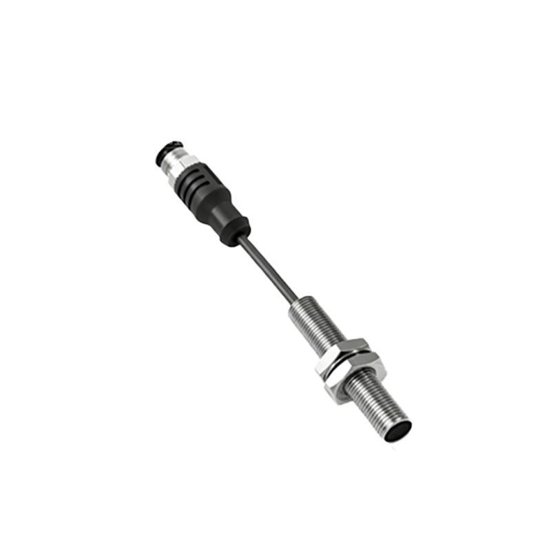
Encasing and protecting all these internal electronics is the Housing or Body. This is typically a robust shell made of metal (like nickel-plated brass or stainless steel) for inductive sensors, or plastic (PBT, PVC) for capacitive and photoelectric types. The housing provides environmental protection against dust, moisture (rated by IP codes), and chemical exposure. It also features a Sensing Face, often made of a specific material (e.g., PTFE for capacitive sensors) that allows the field to pass through while protecting the internal coil or plates.
Critical for installation and electrical connection is the Connection Interface. This can be a pre-attached cable with specified length and color-coded wires, or a standardized connector (e.g., M8, M12 circular connectors). The connection interface supplies power to the sensor (commonly 10-30V DC or 90-250V AC) and carries the output signal back to the control system. Proper shielding within the cable is vital for noise immunity.
Additional components enhance functionality. An Indicator LED is almost standard, providing visual feedback for power status and output activation, crucial for troubleshooting. Some sensors include Potentiometers for fine-tuning sensitivity or hysteresis. Advanced sensors may house a Microcontroller for digital signal processing, programmable logic, and communication via protocols like IO-Link, which allows for parameter setting and detailed diagnostics.
In summary, from the sensing element that interacts with the physical world to the output stage that drives control actions, each component in a proximity sensor has a distinct name and a critical role. Mastery of these terms—oscillator, comparator, housing, output stage—enables precise selection, integration, and troubleshooting, ensuring these versatile devices perform their detection tasks reliably and efficiently across countless applications.