A laser rangefinder sensor is a sophisticated device that measures distance with high precision by utilizing the properties of laser light. Understanding its schematic diagram is crucial for engineers, technicians, and enthusiasts working in fields such as surveying, robotics, autonomous vehicles, and industrial automation. This article breaks down the key components and their interconnections as typically depicted in a standard schematic diagram, providing a clear, non-AI technical overview.
At the heart of the schematic is the Laser Diode (Transmitter). This component generates a coherent, focused beam of light, often in the infrared or visible spectrum. In the diagram, it is represented by a specific electronic symbol, connected to a driver circuit. The driver circuit is critical, as it provides the precise current pulses needed to fire the laser in controlled bursts. This ensures the emitted light pulse is sharp and defined, which is essential for accurate time-of-flight measurements.
The emitted laser beam travels towards the target. A portion of this beam is often immediately diverted internally by a Beam Splitter or a dedicated Start Pulse Detector. This creates a "start" signal, a crucial timing reference point that marks the exact moment the pulse leaves the system. This signal is fed directly into the timing circuitry, initiating the measurement clock.
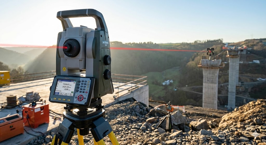
The main beam exits the system through a transmission lens or window, which collimates it to maintain a tight, focused spot over long distances. Upon striking the target, the beam is reflected back towards the sensor. The returning, often much weaker, light is collected by the Receiver Lens or Optics. This lens focuses the scattered return signal onto the core component of the receiver: the Photodetector. Common types include Avalanche Photodiodes (APDs) or PIN photodiodes, chosen for their high sensitivity and fast response times. In the schematic, the photodetector is shown with its biasing circuit, which is vital for its operation, especially for APDs which require a high reverse-bias voltage.
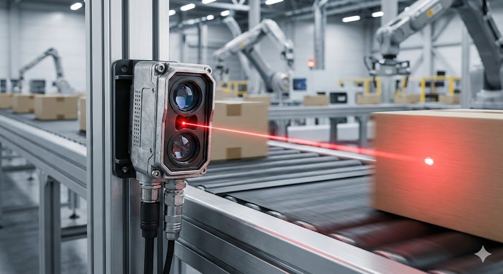
The output of the photodetector is a minute electrical current corresponding to the received light pulse. This signal is then passed through a chain of signal conditioning blocks. First, a Transimpedance Amplifier (TIA) converts the weak current pulse into a usable voltage signal. This signal is typically very noisy. Therefore, it proceeds through Filtering and Amplification Stages—often depicted as operational amplifier configurations—to improve the signal-to-noise ratio (SNR). Band-pass filters are common to eliminate ambient light interference (low-frequency noise) and high-frequency electronic noise.
The cleaned-up signal, now resembling a discernible pulse, enters the Timing and Control Circuitry, which is the computational brain of the system. This block, often centered around a Field-Programmable Gate Array (FPGA), a microcontroller, or a dedicated Time-to-Digital Converter (TDC) IC, has one primary task: to measure the time interval between the "start" pulse (from the beam splitter) and the "stop" pulse (from the received signal). This elapsed time (Δt) is directly proportional to the distance: Distance = (Speed of Light × Δt) / 2.
The schematic shows this block connected to the oscillator or clock crystal that provides the stable time base. The precision of this clock directly determines the measurement resolution. The calculated distance data is then sent to a Data Interface block, which could be a UART, I2C, SPI, or CAN bus interface, allowing the rangefinder to communicate with a host computer, display, or control system.
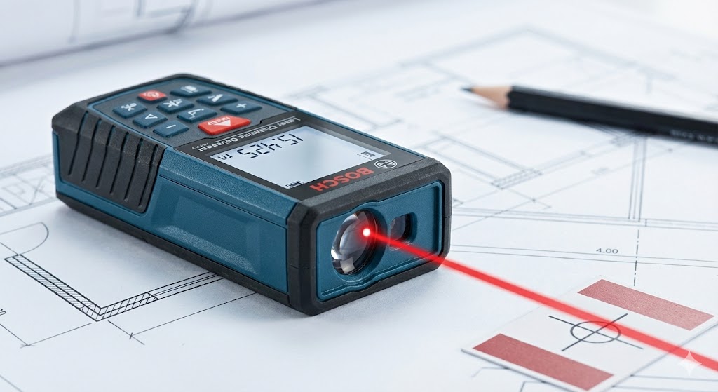
Finally, the entire system is powered by a Power Supply and Regulation Unit. The schematic details voltage regulators, filters, and decoupling capacitors to provide clean, stable voltages to the sensitive analog components (like the APD and amplifiers) and the digital logic circuits, preventing noise from degrading performance.
In summary, a laser rangefinder sensor schematic diagram maps the journey from generating a laser pulse to calculating a precise distance. It visually integrates optics, analog electronics for signal generation and recovery, and digital electronics for precise timing and processing. Reading such a diagram requires an understanding of both optical paths, represented by lines, and electronic circuits, represented by standardized symbols. This synergy of light and electronics enables the non-contact, high-accuracy measurements that define modern laser rangefinding technology.