Proximity sensors are indispensable components in modern industrial automation, enabling the non-contact detection of objects. Their reliable operation, however, hinges entirely on one critical aspect: correct wiring. Improper connections can lead to sensor failure, erratic machine behavior, or even damage to the control system. This guide provides clear, step-by-step instructions for wiring common types of proximity sensors, ensuring a safe and functional installation.
Before handling any wires, the first and most crucial step is to consult the sensor's datasheet. Manufacturers provide specific wiring diagrams, voltage ranges, and output specifications that must be followed. Always disconnect all power sources to the circuit before beginning any wiring work. Gather the necessary tools, including appropriate wire strippers, screwdrivers, and possibly a multimeter for verification.
Most industrial proximity sensors fall into two main categories based on their output configuration: 2-wire and 3-wire sensors. The wiring principles differ significantly between them.
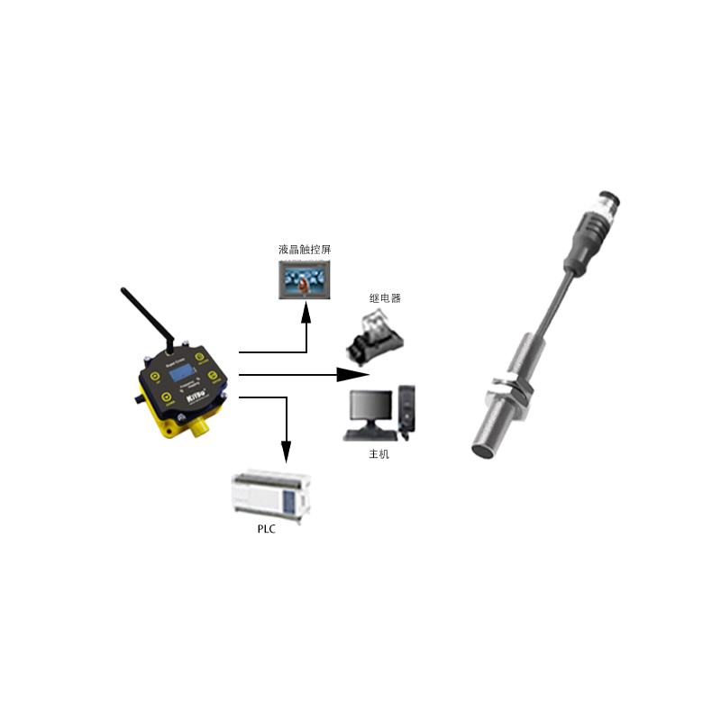
Wiring a 2-Wire Proximity Sensor
The 2-wire sensor is the simplest type, acting like a switch in series with the load. It has only two wires, typically brown and blue, following a common color code (IEC standard). The brown wire connects to the positive DC supply voltage (e.g., +24V). The blue wire connects to the load (e.g., the input of a Programmable Logic Controller - PLC), and the other side of the load is then connected to the power supply's negative terminal (0V). For AC sensors, the brown wire connects to the phase (L) and the blue wire to the load, with the load's other side connected to neutral (N). There is no separate ground wire. It is vital to ensure the sensor's leakage current, when "off," is low enough not to accidentally activate the connected load.
Wiring a 3-Wire Proximity Sensor
The 3-wire sensor is more prevalent and offers better performance. It has three wires: brown (+V), blue (0V or common), and a third output wire, which is usually black for a sinking (NPN) sensor or black (or sometimes white) for a sourcing (PNP) sensor. This design separates the power supply circuit from the output switching circuit.
PNP (Sourcing) Sensor: The output wire switches the positive voltage. Wire the brown to +24V, the blue to 0V. The black output wire connects to your load (e.g., PLC input). The other terminal of the load is then connected to 0V. When the sensor detects an object, it "sources" or provides +24V from the black wire to the load.
NPN (Sinking) Sensor: The output wire switches the ground path. Wire the brown to +24V, the blue to 0V. The black output wire connects to your load. The other terminal of the load must be connected to +24V. When the sensor detects an object, it "sinks" current, completing the circuit to 0V through the black wire.
A common mistake is confusing PNP and NPN wiring or mismatching the sensor type with the PLC input. Always verify the input circuit of your controller.
Wiring a 4-Wire DC Sensor
A 4-wire sensor typically contains two separate outputs, often one Normally Open (NO) and one Normally Closed (NC), or sometimes a PNP and an NPN output in one housing. The standard wires are brown (+V), blue (0V), black (output 1, often NO), and white (output 2, often NC). The wiring follows the same logic as the 3-wire type for each output, but you only use the outputs required for your application. The unused output can be left disconnected.
Shielded Cable and Grounding
For sensors operating in environments with significant electrical noise (e.g., near variable frequency drives or welding equipment), using a shielded cable is highly recommended. The cable's shield, usually a braided metal layer, should be connected to a solid earth ground at the control panel end only. Do not connect the shield at both ends, as this can create ground loops. The drain wire of the shield is typically connected to the grounding terminal inside the panel.
Final Verification and Testing
After all connections are made and double-checked against the datasheet diagram, carefully restore power. Use a multimeter to check the voltage between the sensor's output wire and the common (blue) wire. For a PNP sensor, the voltage should jump from near 0V to near the supply voltage when a target object is presented. For an NPN sensor, the voltage on the output wire should drop from the supply voltage to near 0V