In the evolving landscape of electrical and electronic engineering, precision measurement is paramount. While traditional methods like digital multimeters (DMMs) and LCR meters are staples for resistance measurement, advanced applications increasingly demand non-contact, high-speed, and spatially resolved data. This is where laser sensor technology presents a novel and powerful approach. This guide delves into the principles and methodologies of using laser sensors for indirect resistance measurement, tailored for industry professionals.
The core principle hinges on the relationship between a material's electrical resistance and its thermal or physical properties, which can be probed optically. A laser sensor itself does not measure electrical resistance directly by passing a current; instead, it measures a correlated physical change induced by resistance. The most common and practical technique involves laser-based thermography or thermo-reflectance.
Fundamental Principle: Resistance and Heat Generation
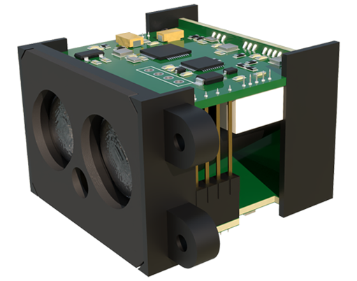
According to Joule's law, when an electrical current (I) passes through a resistor (R), it generates heat (P) proportional to I²R. This localized heating causes a temperature rise in the material. A laser sensor, configured as a precise infrared (IR) radiometer or a laser vibrometer, can detect this thermal response.
Measurement Methodology: A Two-Step Process

The typical setup involves an external current source and the laser sensor system.
1. Stimulus Application: A known current, either DC or a modulated AC signal, is applied to the test specimen (e.g., a thin-film resistor, a solder joint, or a trace on a PCB). The current level must be carefully chosen to generate measurable heat without damaging the component.
2. Laser Detection: The laser sensor is focused on the area of interest.
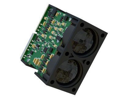
* Using an IR Laser Sensor/IR Camera: The sensor detects the infrared radiation emitted from the heated spot. The intensity of this radiation is directly related to the surface temperature. By calibrating the IR response against known temperature references and knowing the applied current (I), the generated power (P) can be inferred. Using P = I²R, the resistance R can be calculated as R = P / I².
* Using a Laser Vibrometer (for specific cases): The heating causes minute thermal expansion. A laser vibrometer can measure the resulting nanoscale vibrations or displacement of the surface. The amplitude of this thermo-elastic response is correlated with the amount of heat generated, again allowing for the back-calculation of resistance.
System Components and Setup
A functional system requires:
* Laser Source & Detector: A focused, stable laser (often in the IR or visible spectrum) and a sensitive photodetector.
* Current Source: A precision programmable current source to provide the excitation signal.
* Optical Components: Lenses and mirrors to focus the laser spot precisely on the target area, which can be as small as a few micrometers.
* Data Acquisition & Processing Unit: Software to capture the laser detector's signal, synchronize it with the current stimulus, and perform the necessary calculations to derive resistance.
Key Advantages for Industrial Applications
* Non-Contact: Eliminates the need for physical probes, preventing loading effects and damage to delicate components like MEMS devices or ultra-fine wires.
* High Spatial Resolution: The focused laser spot allows for mapping resistance variations across a surface, invaluable for identifying defects like voids in solder balls, inhomogeneities in resistive films, or cracked traces.
* High-Speed Dynamic Measurement: Can measure rapid resistance changes in real-time, useful for studying fuse blowing, thermal runaway in semiconductors, or material characterization under pulse conditions.
* Accessibility: Can measure components embedded within assemblies or in harsh environments where physical probe contact is impossible.
Challenges and Considerations
* Calibration: The system requires careful calibration to relate the optical signal (IR emission or displacement) to absolute temperature and, consequently, to power dissipation. Emissivity of the target material significantly affects IR measurements.
* Material Dependence: The thermo-optical properties (thermal conductivity, emissivity, expansion coefficient) of the material under test must be known or characterized.
* Heat Dissipation: The accuracy depends on the assumption that most heat is generated at the measured spot. Conductive heat loss to the substrate or surroundings must be minimized or accounted for in the model.
* Cost and Complexity: The system is significantly more complex and expensive than a standard ohmmeter, justifying its use primarily in R&D, failure analysis, and high-value manufacturing.
Typical Use Cases
* Failure Analysis: Locating high-resistance faults (hot spots) in integrated circuits (ICs) and power electronics.
* Quality Control: Mapping sheet resistance uniformity of large-area transparent conductive films (e.g., ITO) used in displays.
* Microelectronics Research: Characterizing the resistance of nanowires, graphene layers, or other nanomaterials.
* Solder Joint Integrity Testing: Detecting poor solder joints in Ball Grid Arrays (BGAs) by identifying joints with anomalous resistance via their thermal signature.
In conclusion, measuring resistance with laser sensors is an advanced, indirect thermographic technique. It translates the electrical property of resistance into a measurable thermal signature detected by a precision laser system. While not a replacement for conventional direct measurement tools, it fills a critical niche for non-contact, high-resolution, and dynamic resistance analysis in advanced electrical engineering and microelectronics. Successful implementation demands a solid understanding of both electrical thermal principles and optical sensing technology.