Inductive proximity sensors are widely used in industrial automation for non-contact detection of metallic objects. These robust and reliable devices operate on the principle of electromagnetic induction, offering long service life and high switching frequencies even in harsh environments. Understanding the internal composition of an inductive sensor is key to selecting and applying it correctly.
At the heart of every inductive proximity sensor is an oscillator circuit. This circuit generates a high-frequency alternating electromagnetic field that radiates from the sensor's active face, typically made of a ferrite core. The oscillator's coil is wound around this core, creating the oscillating field. When a conductive metal target enters this field, eddy currents are induced on the surface of the target. These eddy currents draw energy from the oscillator, causing a reduction in the amplitude of the oscillation. This amplitude change is the primary detection signal.
The sensor's electronics are not limited to the oscillator. A trigger circuit, or Schmitt trigger, continuously monitors the oscillator's amplitude. Once the amplitude drops below a predefined threshold—corresponding to the sensor's specified sensing distance—the trigger circuit activates. This activation changes the state of the sensor's output. The output stage is the final key electronic component. It amplifies the trigger signal to drive an external load, such as a PLC input, relay, or indicator lamp. Common output types include NPN (sinking), PNP (sourcing), analog (4-20mA or 0-10V), and push-pull configurations.
Encasing and protecting these sensitive electronic components is a robust housing. For cylindrical sensors, this is typically made of nickel-plated brass, stainless steel, or industrial-grade plastics like PBT. The housing provides mechanical strength, environmental sealing (often rated IP67 or IP69K), and electromagnetic shielding. The shielding is crucial; it confines the electromagnetic field to the front of the sensor, preventing sideward detection and improving stability. A non-shielded variant exists for applications requiring longer range or side detection, but it is more susceptible to interference from adjacent metal.
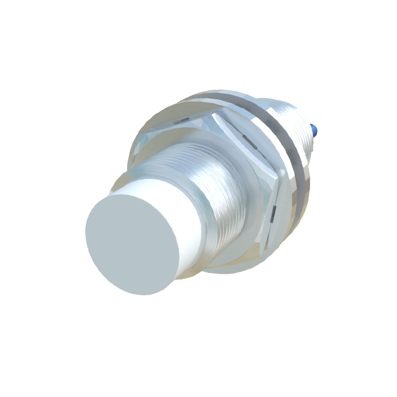
The sensor's face, or sensing surface, is a critical mechanical part. It is usually a wear-resistant material, often the same as the housing or a specialized ceramic, designed to withstand physical abrasion from passing targets. Behind this face sits the ferrite core, which focuses the electromagnetic field. Wires or a pre-attached cable with a standardized connector (e.g., M8, M12) provide power and carry the output signal. For some models, an LED status indicator is integrated into the housing, providing visual confirmation of power and switching state.
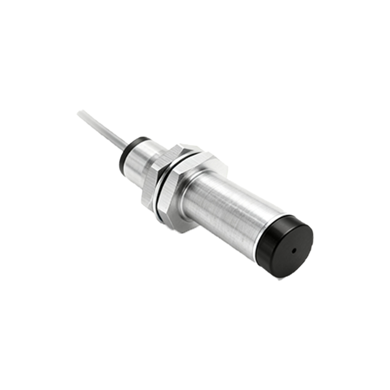
The performance of an inductive sensor is defined by its components. The coil's design and the oscillator's frequency determine the nominal sensing distance and the type of metal it can best detect. For instance, steel is detected at the full rated distance, while non-ferrous metals like aluminum or copper cause a reduction factor, requiring a larger target or closer proximity. The hysteresis, a built-in difference between the switch-on and switch-off points, is engineered by the trigger circuit to prevent output chattering when a target is at the edge of the sensing range.
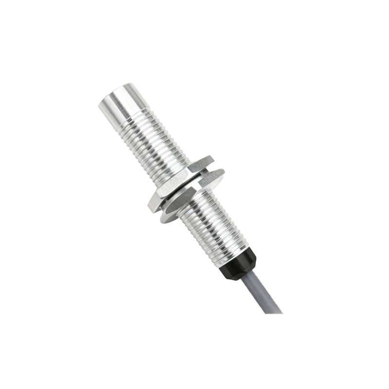
In summary, an inductive proximity sensor is a sophisticated integration of electromagnetic and electronic principles within a rugged package. Its core components—the oscillator coil, ferrite core, trigger circuit, output stage, and shielded housing—work in unison to provide a precise, wear-free, and reliable solution for position sensing and object detection in countless automated systems, from conveyor lines to robotic cells. Proper selection involves matching these component characteristics, such as sensing distance, housing material, output type, and shielding, to the specific application requirements.