Proximity sensors are indispensable components in modern industrial automation, enabling non-contact detection of objects without physical interaction. At the heart of their functionality lies the main circuit, which dictates performance, reliability, and application suitability. This article delves into the design principles, configurations, and practical considerations of main circuits in inductive, capacitive, and photoelectric proximity sensors, tailored for engineers and technical professionals in the electrical and automation industries.
Inductive proximity sensors, widely used for metal detection, incorporate an oscillator circuit as the core of their main circuit. The oscillator generates a high-frequency electromagnetic field via a coil and capacitor tank circuit. When a metallic object enters this field, eddy currents are induced, causing a change in oscillation amplitude or frequency. This alteration is detected by a threshold circuit, which triggers the output stage—typically a solid-state switch (e.g., NPN or PNP transistor) or relay. Key design considerations include noise immunity, achieved through shielding and filtering components, and temperature stability, managed via compensated components. For instance, in conveyor systems, inductive sensors with robust main circuits ensure precise detection of metal parts even in harsh environments with electrical interference.
Capacitive proximity sensors, capable of detecting both metallic and non-metallic materials, rely on a capacitance-sensitive oscillator in their main circuit. The sensor electrode forms one plate of a capacitor, with the target object acting as the other plate. As the object approaches, the capacitance increases, shifting the oscillator frequency. A demodulator circuit converts this change into a voltage signal, processed by a comparator to activate the output. Design challenges include sensitivity adjustment to avoid false triggers from humidity or material variations. In packaging industries, capacitive sensors with adjustable main circuits reliably detect plastic or liquid levels, with circuits often incorporating trimmer potentiometers for fine-tuning.
Photoelectric proximity sensors utilize optical principles, with main circuits centered on an emitter-receiver pair. The emitter circuit drives an infrared or laser LED, while the receiver circuit processes reflected or transmitted light via a phototransistor or photodiode. A signal conditioning stage amplifies and filters the received signal, feeding it to a logic circuit for output switching. Advanced designs incorporate modulation techniques (e.g., pulsed light) to enhance immunity to ambient light. In automated warehouses, photoelectric sensors with modulated main circuits accurately detect objects over long distances, with circuits optimized for low power consumption and high-speed response.
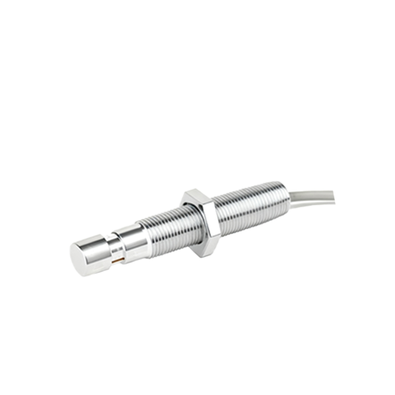
Common to all proximity sensor main circuits is the power supply section, which may include voltage regulators, surge protection, and reverse-polarity safeguards. For DC sensors, circuits often integrate constant-current sources to ensure stable operation across voltage fluctuations. Output configurations vary: two-wire sensors combine power and output in a single loop, while three-wire and four-wire designs separate supply and signal paths for improved precision. In automotive assembly lines, three-wire inductive sensors with short-circuit-protected main circuits enhance safety and durability.
When selecting or designing a main circuit, engineers must evaluate factors like operating voltage (typically 10-30 VDC or 90-250 VAC), load current (up to 200 mA for solid-state outputs), and response time (microseconds to milliseconds). EMI/RFI compliance is critical, achieved through PCB layout optimization (e.g., ground planes) and component selection such as ferrite beads. For extreme conditions, like mining or chemical plants, circuits are encapsulated and rated for IP67 or higher.
Innovations in main circuit technology focus on miniaturization and smart features. Integrated circuits (ICs) now combine oscillator, comparator, and output stages into single chips, reducing footprint and cost. Some sensors embed diagnostic functions, like output status LEDs or fault detection circuits, communicating via IO-Link for predictive maintenance. In robotics, compact sensors with IC-based main circuits enable precise positioning and collision avoidance.
In summary, the main circuit is the backbone of proximity sensor performance, balancing detection accuracy, environmental resilience, and energy efficiency. By understanding its design nuances, engineers can optimize sensor integration across diverse applications, from manufacturing and logistics to energy and beyond. As Industry 4.0 advances, expect further evolution in circuit designs toward connectivity and adaptability.