In the rapidly evolving landscape of industrial automation, the introduction of new generation proximity sensors marks a significant leap in precision, reliability, and functionality. These advanced devices, employing technologies like enhanced inductive, capacitive, and even ultrasonic principles, offer superior performance in detecting the presence or absence of objects without physical contact. However, their sophisticated design necessitates a meticulous and informed calibration process to ensure optimal operation within complex systems. This article outlines the critical calibration procedures and best practices for integrating these cutting-edge sensors.
The cornerstone of effective calibration is a thorough pre-installation assessment. Begin by consulting the manufacturer's datasheet for the specific sensor model. Key parameters to note include the nominal sensing distance (Sn), operating voltage range, output type (e.g., NPN/PNP, analog, IO-Link), and any built-in diagnostic features. Ensure the sensor is compatible with the controller (PLC) and the electrical characteristics of your system. Visually inspect the sensor for any physical damage and verify the environmental ratings (IP, NEMA) are suitable for the installation site, considering factors like temperature extremes, humidity, and potential exposure to chemicals or washdowns.
Mounting is the first active step influencing calibration. For inductive and capacitive sensors, the presence of surrounding metal (proximity to machine frames, brackets, or other sensors) can create a "shielding effect," reducing the effective sensing range. Adhere strictly to the manufacturer's recommended minimum clearance distances. Use non-ferromagnetic mounting hardware when possible. The sensor must be securely fastened to prevent vibration-induced misalignment, which can cause erratic triggering. For applications requiring precise position detection, ensure the sensor is aligned perpendicular to the target's approach path.
Electrical connection must be executed with precision. Follow the wiring diagram explicitly, connecting the brown wire (typically +V), blue wire (0V or common), and black wire (load or signal output) correctly. Incorrect polarity can damage the sensor. After powering the circuit, observe the sensor's indicator LED. Most new models feature multi-color LEDs that provide status information: steady on for power, blinking for short-circuit protection, or changing color to indicate target detection state. This initial diagnostic is invaluable.
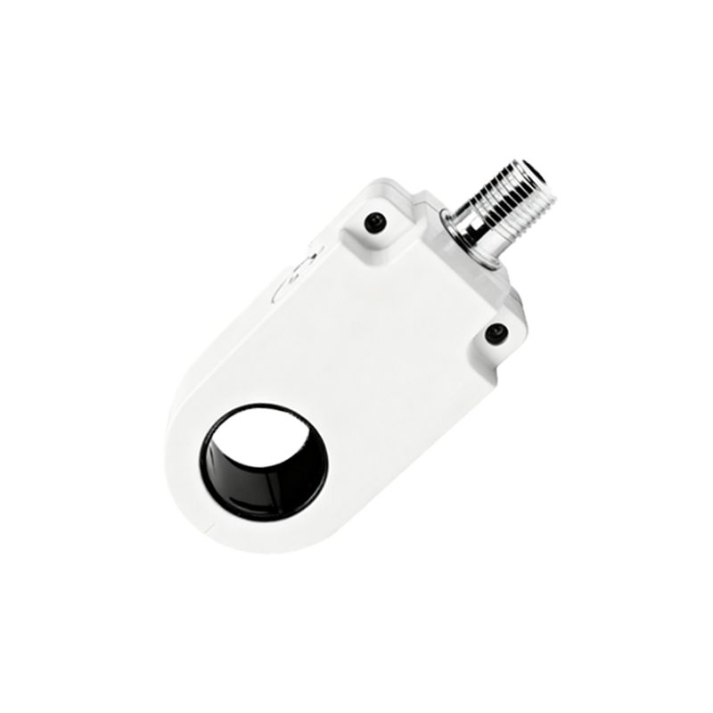
The core calibration process involves setting the sensing distance and response characteristics. For standard two-wire or three-wire DC sensors, the primary adjustment is often the sensitivity potentiometer or teach-in function. The procedure generally involves the following steps:
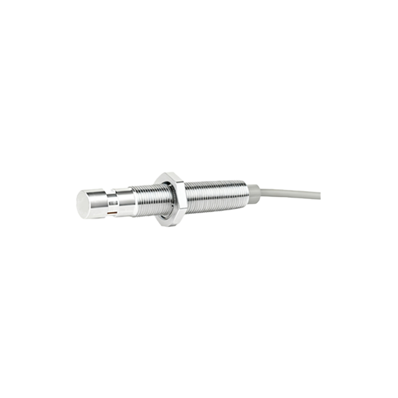
1. Position the Standard Target: Use the target material and size specified by the manufacturer (usually a square of mild steel for inductive sensors). Position it at the exact nominal distance (Sn) from the sensing face.
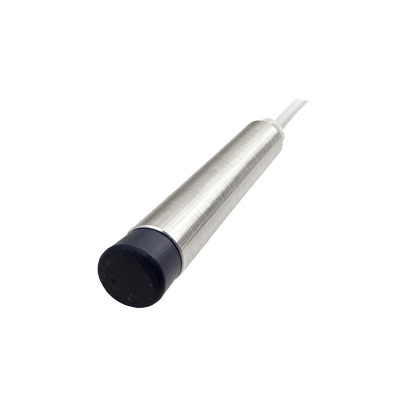
2. Adjust Sensitivity: With the target in place, slowly adjust the sensitivity potentiometer clockwise until the sensor's output activates (LED changes, output switches). Then, slowly rotate the potentiometer counterclockwise until the output just deactivates. The ideal setting is typically midway between these two points. This ensures a stable operating point with a sufficient safety margin against false triggers due to temperature drift or minor target variations.
3. Verify Hysteresis: Move the target toward and away from the sensor several times. Note the difference between the "switch-on" point and the "switch-off" point; this is the hysteresis, a built-in feature to prevent chatter. Ensure this behavior is consistent.
4. Test with Actual Target: Replace the standard target with the actual application target. Verify reliable detection across the entire required range of motion. For factors like target color, material composition, or surface finish (which affect capacitive and optical sensors), further fine-tuning may be necessary.
For intelligent sensors with IO-Link or analog outputs, calibration is frequently software-driven. Connect the sensor to an IO-Link master or configuration tool. Parameters such as switching thresholds, output delay timers (on/off delay), and operating modes (e.g., window mode, dynamic background suppression) can be configured digitally. Analog sensors require scaling the output signal (e.g., 4-20mA, 0-10V) to correspond to the desired measurement range in the PLC program. Always document these software settings for future reference and troubleshooting.
Post-calibration validation is non-negotiable. Subject the sensor to real-world operating conditions. Perform multiple cycles of the machine or process, introducing potential variances like slightly different target positions, temperature changes, or electrical noise from nearby motors. Monitor the sensor's performance for consistency. Utilize any advanced diagnostics, such as signal strength indicators or condition monitoring data available via IO-Link, to predict maintenance needs.
Finally, establish a routine maintenance and recalibration schedule. Even the most robust sensors can experience drift over time due to environmental stress or component aging. Periodic checks against a known standard target will confirm ongoing accuracy and prevent unplanned downtime. By adhering to these structured calibration protocols, engineers can fully harness