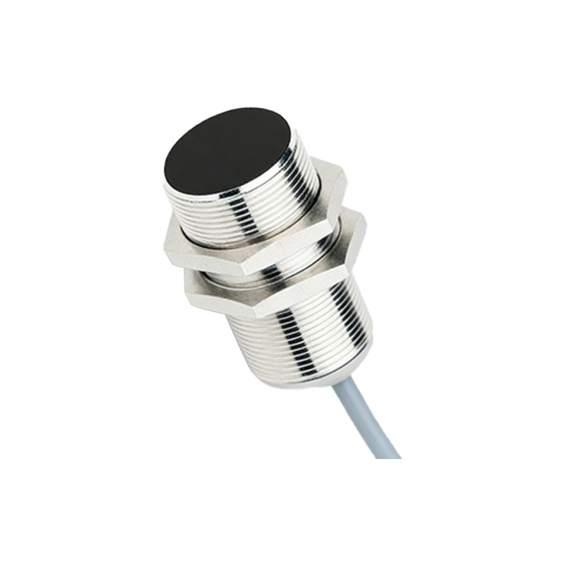
In industrial automation and control systems, proximity sensors are indispensable components for detecting the presence or absence of objects without physical contact. However, a persistent and frustrating issue that many engineers and maintenance technicians encounter is the phenomenon of proximity sensors "jumping" or triggering false alarms. This erratic behavior can lead to production downtime, quality control issues, and increased maintenance costs. Understanding the root causes of this problem requires a systematic examination of the sensor's operating principles, installation environment, and external influencing factors.
At its core, a proximity sensor operates by generating an electromagnetic field or a beam of radiation. Inductive sensors detect metallic objects, capacitive sensors detect both metallic and non-metallic materials, and photoelectric sensors use light beams. A "jump" or false trigger occurs when the sensor's output switches state without a valid target within its specified sensing range. The first and most common culprit is electrical noise or interference. In industrial settings, powerful motors, variable frequency drives (VFDs), welding equipment, and even other sensors can generate significant electromagnetic interference (EMI) or radio frequency interference (RFI). This noise can be inductively or capacitively coupled into the sensor's wiring or directly influence its internal circuitry, causing momentary false readings. Shielding sensor cables, using twisted-pair wires, ensuring proper grounding (star-point grounding is often recommended), and installing ferrite cores or noise filters can dramatically mitigate this issue. Additionally, maintaining a safe distance between sensor cables and high-power lines is a fundamental but often overlooked practice.
Environmental conditions pose another significant challenge. For inductive and capacitive sensors, the accumulation of metallic dust, chips, or conductive fluids on the sensor's active face can effectively alter its sensing field. A layer of such material can be misinterpreted as a target, causing constant or intermittent activation. Similarly, for photoelectric sensors, dust, fog, oil mist, or condensation on the lens can scatter or block the light beam, leading to unreliable operation. Regular cleaning schedules and selecting sensors with appropriate IP (Ingress Protection) ratings for the environment are critical preventive measures. Extreme temperature fluctuations can also affect the stability of the sensor's electronic components and the oscillation circuit in inductive sensors, leading to drift in the sensing distance and potential false triggers.
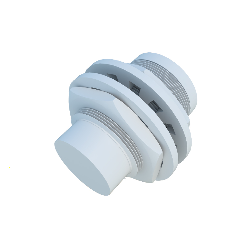
Mechanical factors are frequently the source of intermittent problems. Vibration and shock can cause loose connections at the terminal blocks, internal solder joint fractures, or even slight physical movement of the sensor itself. If a sensor mounted on a vibrating machine shifts even a millimeter, its relationship to the target changes, potentially causing it to trigger erratically. Ensuring robust mechanical mounting using proper brackets and locknuts, and employing vibration-dampening mounts where necessary, is essential. The target object itself must also be considered. Is it the correct size and material for the sensor type? Is it moving at a speed within the sensor's response frequency? A target that is too small, made of the wrong type of metal (e.g., aluminum versus steel for an inductive sensor), or passing by at an extreme angle may only intermittently disrupt the sensor field sufficiently to cause an unstable signal.
Finally, we must consider the sensor's own health and the integrity of the supply power. Over time, internal components can degrade. Capacitors may dry out, and oscillator coils can weaken, leading to reduced sensitivity or unstable operation. A failing sensor might begin to "chatter." Equally important is the quality of the DC power supply. Voltage spikes, sags, or ripple on the 24V DC line—common in plants with large inductive loads—can directly cause sensor malfunctions. Using a regulated and filtered power supply dedicated to control circuitry is a best practice. Additionally, ensuring the load (e.g., a PLC input or relay) does not exceed the sensor's maximum current rating is vital to prevent damage and unstable operation.
Troubleshooting a "jumping" proximity sensor demands a methodical approach. Start with a visual inspection for contamination, damage, and loose connections. Use an oscilloscope to monitor the sensor's output signal and the DC supply line for noise or instability. Temporarily replace the sensor with a known-good unit to isolate the fault. Log environmental data such as temperature and the operation of nearby heavy machinery when faults occur. By systematically addressing the potential causes—electrical noise, environmental contaminants, mechanical instability, target suitability, and power quality—engineers can restore reliability to their sensing systems and ensure seamless, uninterrupted automation processes. The key is to remember that the sensor is part of a larger system, and its performance is inextricably linked to its installation and operating context.