Proximity sensors are essential components in modern industrial automation, robotics, and safety systems. Their ability to detect the presence or absence of objects without physical contact makes them invaluable. This article delves into the structural design and manufacturing process of inductive and capacitive proximity sensors, the two most common types in industrial applications.
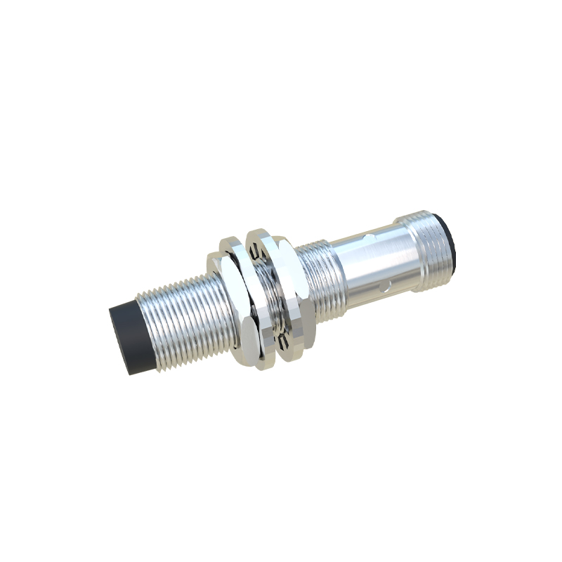
The core structure of an inductive proximity sensor consists of four main parts: the coil, oscillator, detection circuit, and output circuit, all housed within a robust casing. The coil, typically wound around a ferrite core, generates an electromagnetic field when the oscillator supplies a high-frequency current. When a metallic object enters this field, eddy currents are induced on the object's surface, causing a change in the oscillation amplitude. The detection circuit monitors this change and triggers the output circuit (usually a solid-state switch) to change state. The housing is critical, often made from nickel-plated brass or stainless steel for environmental protection and shielding. Key design considerations include sensing distance, which depends on coil size and oscillator frequency, and the incorporation of features like short-circuit and overload protection.
Capacitive proximity sensors share a similar modular structure but operate on a different principle. They contain an electrode that forms one plate of a capacitor, with the target object acting as the other plate. The internal circuitry includes an oscillator, threshold detector, and output stage. The structure includes a sensing face often made from a material like PTFE or ceramic that allows the electric field to penetrate. These sensors can detect both metallic and non-metallic materials, including liquids and powders. The housing must ensure proper field projection while preventing false triggers from the mounting environment. Shielding is a major design factor; unshielded versions have a larger sensing field but are more susceptible to interference, while shielded types have a more directed field for flush mounting.
The manufacturing process begins with the fabrication of the core sensing element. For inductive sensors, this involves precision winding of the coil onto the ferrite core. Automated winding machines ensure consistency in the number of turns and tension, which directly impacts the sensor's sensitivity and range. The coil is then potted or encapsulated in a resin to protect it from vibration and moisture. The oscillator and detection ICs are mounted on a printed circuit board (PCB) using surface-mount technology (SMT) for compactness and reliability.
The housing components are manufactured separately, typically through machining for metal parts or injection molding for polymer-based sensors. Critical steps include ensuring the precise dimensions of the sensing face and the thread for mounting. For inductive sensors, the front face is often a specific thickness of a non-ferrous metal like stainless steel, which allows the magnetic field to pass through while providing a wear-resistant surface.
Assembly is a sequential process. The PCB assembly is first fitted into the housing. Electrical connections between the coil and the PCB are made via soldering or spring contacts. The unit is then sealed, often using laser welding for metal housings or ultrasonic welding for plastic types, to achieve a high Ingress Protection (IP) rating, such as IP67 or IP69K. Following assembly, each sensor undergoes rigorous calibration and testing. This includes checking the switching point at the rated sensing distance, testing temperature drift, and verifying output signal integrity under load. Environmental tests for vibration, shock, and humidity are also conducted to ensure durability.
Recent advancements in structure and manufacturing focus on miniaturization and enhanced functionality. The use of Application-Specific Integrated Circuits (ASICs) allows for more complex signal processing in a smaller footprint. 3D printing is being explored for prototyping and even producing complex housing geometries that are difficult to machine. Furthermore, the integration of IO-Link communication capability requires adding a micro-controller and related circuitry to the standard structure, enabling smart sensor features like parameterization and condition monitoring.
In conclusion, the performance and reliability of a proximity sensor are fundamentally tied to its structural design and the precision of its manufacturing process. A deep understanding of electromagnetic or capacitive field theory must guide the mechanical and electronic design to achieve the desired sensing characteristics. As Industry 4.0 demands more intelligent and connected devices, sensor structures will continue to evolve, incorporating more electronics and communication interfaces while maintaining the ruggedness required for harsh industrial environments.