Proximity sensors are indispensable components in modern industrial automation, robotics, and machinery. They provide non-contact detection of objects, enabling precise control, safety interlocks, and process monitoring. However, the reliable operation of these sensors is often compromised by a pervasive and challenging issue: cable interference. This phenomenon can lead to false triggering, reduced sensing range, signal degradation, and ultimately, system downtime. Understanding the sources, mechanisms, and solutions for cable interference is critical for any engineer designing or maintaining automated systems.
Cable interference in proximity sensor systems primarily manifests as electromagnetic interference (EMI). This can be categorized into two main types: conducted interference and radiated interference. Conducted interference travels along the power and signal cables themselves, often introduced from noisy power supplies, variable frequency drives (VFDs), or other high-current switching devices sharing the same electrical network. Radiated interference, on the other hand, is transmitted through the air and can be picked up by the sensor cable, which acts as an unintended antenna. Common sources include radio transmitters, welding equipment, and arcing from motors or relays.
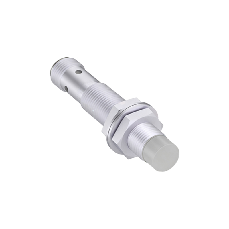
The physical layout of the cable is a significant factor. Running sensor cables in parallel with high-voltage power cables over long distances creates capacitive and inductive coupling. The changing magnetic field from the power cable induces a voltage in the adjacent sensor cable (inductive coupling), while the electric field can cause current leakage (capacitive coupling). Both effects inject noise into the sensor signal. Furthermore, if the cable shielding is compromised—damaged, improperly terminated, or non-existent—the system becomes vastly more susceptible to radiated EMI.
The type of proximity sensor also influences its susceptibility. Inductive sensors, which detect metallic objects using a high-frequency oscillating electromagnetic field, are particularly sensitive to external magnetic fields from nearby sensors or sources. Capacitive sensors, which detect changes in capacitance, can be affected by stray capacitance from nearby cables or grounded objects. Even photoelectric sensors can experience interference if their signal cables are not properly shielded from EMI.
Mitigating cable interference requires a systematic approach, starting at the design and installation phase. The most fundamental rule is proper cable routing. Always maintain maximum practical separation between sensor cables and power cables. Industry standards often recommend a minimum separation of 12 inches (30 cm), but greater distances are preferable. If cables must cross, they should do so at a 90-degree angle to minimize the length of parallel run and thus the coupling area.
Shielding is the next line of defense. Use high-quality, shielded cables specifically designed for sensor applications. The shield, typically a braided copper mesh or foil, must be grounded correctly at one end only, usually at the controller or PLC end. Grounding at both ends can create ground loops, where potential differences between ground points drive currents through the shield, ironically introducing more noise. The shield connection must be secure and have low impedance.
For severe noise environments, employing twisted-pair cables is highly effective. Twisting the signal and return wires ensures that any induced noise appears as a common-mode signal (equal in both wires), which the differential input of the sensor amplifier or controller can reject. Combining twisted pairs with an overall shield provides excellent noise immunity.
At the system level, consider using filters. Ferrite cores or beads clamped around the sensor cable near the connection points can absorb high-frequency noise. Some sensors and controllers have built-in filtering or offer adjustable sensitivity and response time settings; increasing the response time can help filter out brief noise spikes. For analog sensors, using a 4-20 mA current loop signal is inherently more noise-resistant than a 0-10V voltage signal over long distances.
Power supply quality is paramount. Ensure sensors are powered by a clean, regulated, and dedicated power supply if possible. Isolating sensor circuits from noisy loads using separate transformers or power conditioners can prevent conducted interference from entering the system. In applications with numerous sensors, using a centralized, shielded junction box with proper grounding practices helps organize and protect cabling.
Finally, rigorous testing and maintenance are essential. After installation, test the system under all expected operating conditions, including the activation of all nearby machinery. Use an oscilloscope to monitor the sensor signal for noise. Regularly inspect cables for physical damage to the insulation or shield. A proactive approach to identifying and addressing interference sources will ensure the long-term reliability and accuracy of your proximity sensing systems, safeguarding productivity and preventing costly unplanned stoppages.