Setting up a laser sensor correctly is crucial for ensuring accurate measurements, reliable operation, and long-term performance in industrial applications. Whether used for distance measurement, object detection, alignment, or quality control, a properly configured laser sensor can significantly enhance system efficiency. This guide provides a comprehensive, step-by-step approach to laser sensor installation and configuration, tailored for electrical engineers and technicians working in automation, manufacturing, or R&D environments.
First, understand the sensor specifications. Before mounting, review the datasheet for key parameters such as measurement range, accuracy, resolution, response time, laser class (typically Class 1 or 2 for safety), output type (analog, digital, or serial), and environmental ratings (IP protection, temperature range). Ensure the sensor matches the application requirements—for instance, a high-precision triangulation sensor for micron-level measurements versus a time-of-flight sensor for longer ranges.

Select an appropriate mounting location. The sensor should be securely fixed to a stable surface, minimizing vibrations that can affect readings. Consider the target's properties: surface color, material, and reflectivity can influence the laser's return signal. For diffuse surfaces, ensure sufficient reflectivity; for shiny or transparent objects, specialized sensors or filters may be needed. Align the sensor perpendicular to the target surface to avoid angular errors, and maintain a consistent operating distance within the specified range.
Electrical connections must follow safety standards. Power the sensor according to its voltage rating (commonly 12-24 VDC), using shielded cables to reduce electromagnetic interference. Connect output wires to the control system (PLC, microcontroller, or data logger), verifying signal compatibility—for example, a 4-20 mA analog output for process control or a PNP/NPN digital signal for object detection. Implement proper grounding to prevent noise and ensure stable operation.
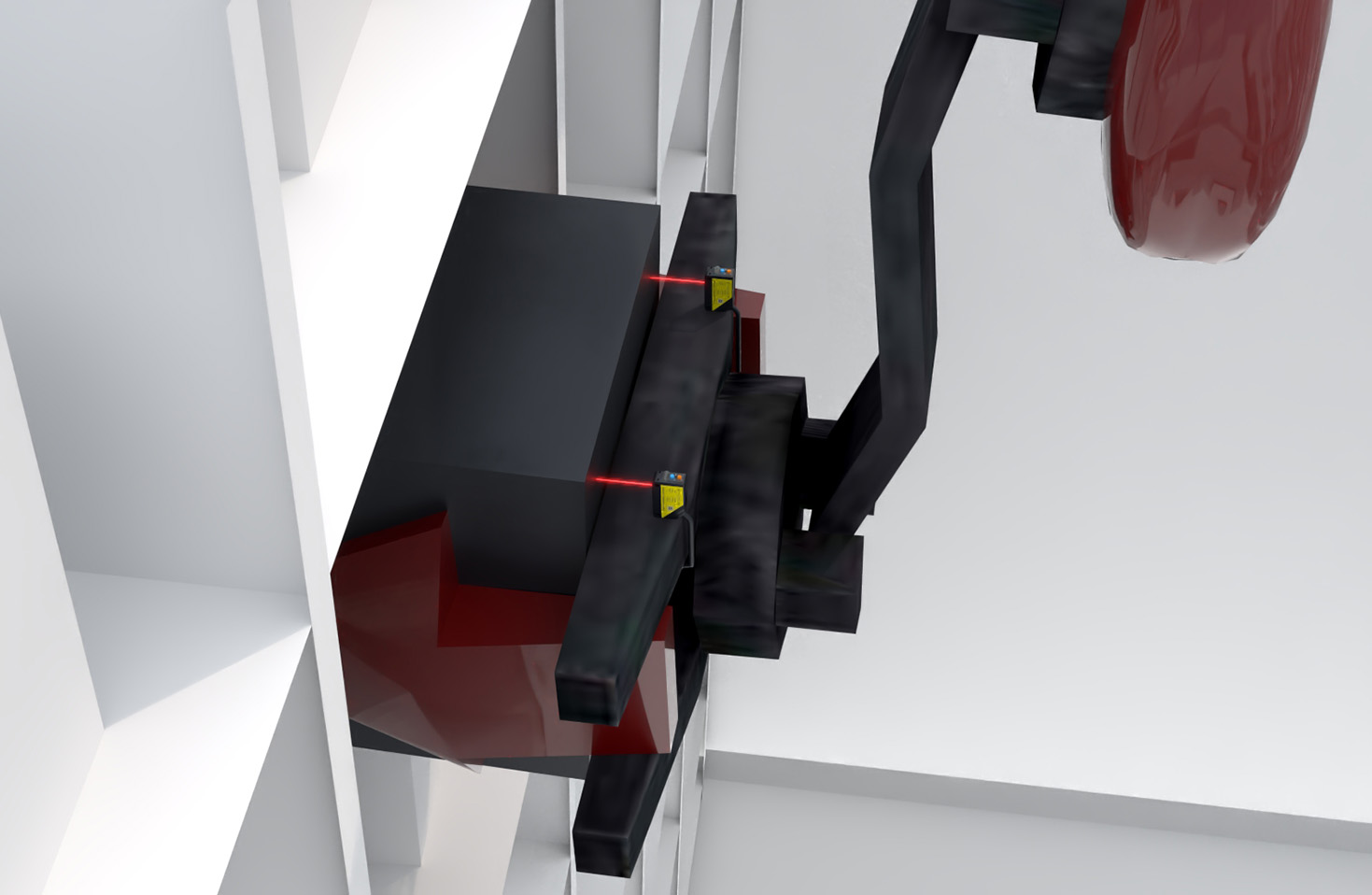
Configuration is typically done via software or onboard controls. Many modern laser sensors offer intuitive software interfaces for setting parameters like measurement mode, output scaling, and filtering. Calibrate the sensor using a known reference target: place the target at a precise distance, adjust the zero point and span, and validate readings across the range. Enable filtering options (e.g., moving average) to smooth data in noisy environments, but avoid over-filtering that may delay response.
Testing and validation are essential. Perform functional tests with actual targets under operating conditions. Check for consistency, repeatability, and drift over time. Use an oscilloscope or data acquisition system to monitor output signals for stability. Environmental factors like ambient light, dust, or temperature fluctuations should be mitigated—install protective housings or use sensors with built-in compensation features.
Maintenance ensures longevity. Regularly clean the lens with a soft, lint-free cloth to prevent contamination from debris or oils. Inspect cables and connectors for wear, and verify calibration periodically, especially after mechanical shocks or environmental changes. Document settings and keep a log for troubleshooting.
In summary, successful laser sensor setup hinges on meticulous planning, precise installation, and thorough validation. By adhering to manufacturer guidelines and industry best practices, engineers can optimize sensor performance, reduce downtime, and achieve reliable results in diverse applications from robotics to metrology.