In industrial automation and machinery control, laser proximity sensors are indispensable components for precise non-contact detection. Their high accuracy, fast response, and long sensing range make them superior to many other sensing technologies. However, their effectiveness hinges entirely on correct installation and wiring. Improper wiring can lead to sensor failure, inaccurate readings, or even damage to the sensor and connected control systems. This guide provides a comprehensive, step-by-step approach to wiring a laser proximity sensor, adhering to standard industry practices and safety protocols.
Before handling any wiring, the paramount rule is safety. Always disconnect and lock out all power sources to the control panel and the machine. Verify the absence of voltage using a properly rated multimeter. Wear appropriate personal protective equipment (PPE). Secondly, thoroughly read the sensor's datasheet and installation manual. Specifications vary significantly between models (e.g., diffuse, retro-reflective, through-beam) and output types (e.g., NPN, PNP, analog, IO-Link). Identify the exact pinout diagram, voltage requirements (commonly 10-30V DC), output current rating, and connection designations.
A typical 3-wire or 4-wire DC laser proximity sensor will have the following terminals:
1. Brown (or Red) Wire: This is the positive supply voltage line (+V). It must be connected to the positive terminal of your DC power supply (e.g., 24V DC).
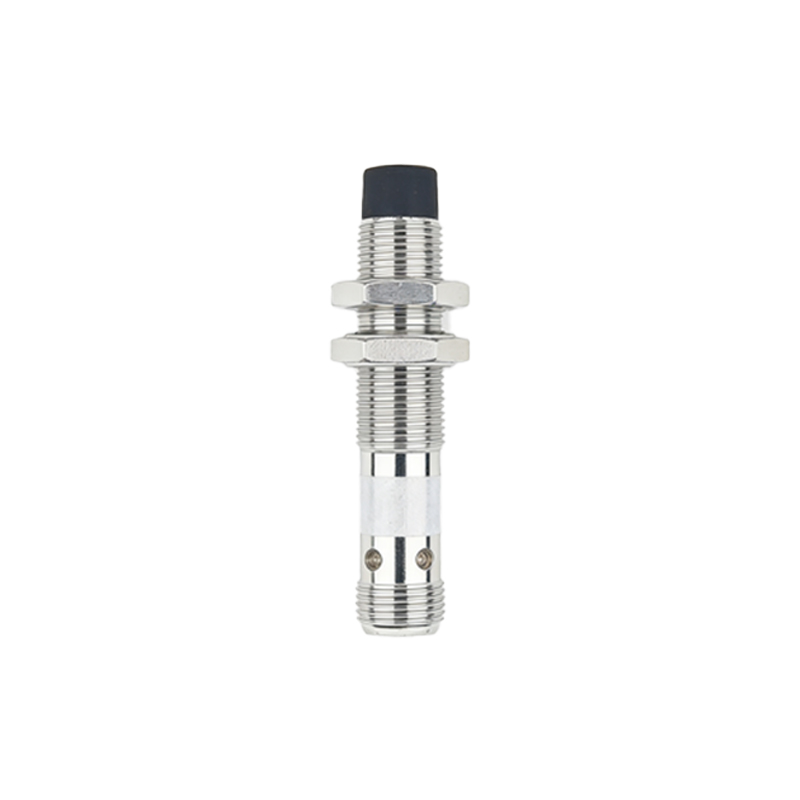
2. Blue (or Black) Wire: This is the negative supply voltage line (0V or GND). It must be connected to the negative terminal/ground of your DC power supply and the common ground of the controller (e.g., PLC).
3. Black (or White) Wire: This is the output signal line. Its behavior depends on the sensor's logic (Sourcing/PNP or Sinking/NPN).
For a PNP (Sourcing) Sensor: The output acts as a positive voltage source. When the sensor detects an object, it switches the output line to connect to the internal +V supply, sending a positive signal to the load (e.g., PLC input).
For an NPN (Sinking) Sensor: The output acts as a ground switch. When the sensor detects an object, it switches the output line to connect to the internal 0V/GND, sinking current from the load.
4. White (or Gray) Wire: Often present as a second output for complementary signal, teach-in function, or analog output. Always consult the manual.
Wiring Procedure:
Step 1: Power Supply Connection.
Connect the sensor's Brown wire to the positive DC supply terminal (e.g., +24V). Connect the sensor's Blue wire to the negative/ground terminal of the same DC supply. This powers the sensor's internal circuitry. Use ferrules on stranded wires for a secure, reliable connection in terminal blocks.
Step 2: Output Signal Connection to Controller (PLC).
This is the most critical step and depends on your sensor and PLC input type.
Wiring a PNP Sensor to a PLC Sinking Input: Most PLC digital inputs are configured as sinking (common to negative). For this setup:
Connect the sensor's Black (output) wire to the designated PLC input terminal (e.g., I0.0).
Connect the common terminal of that PLC input module (often labeled "M" or "COM") to the negative/ground of the power supply (same as the sensor's blue wire).
When the PNP sensor activates, it sources current into the PLC input, completing the circuit to common negative, thus registering a logic HIGH/1.
Wiring an NPN Sensor to a PLC Sourcing Input: If your PLC input module is sourcing (common to positive):
Connect the sensor's Black (output) wire to the designated PLC input terminal.
Connect the common terminal of that PLC input module to the positive of the power supply (same as the sensor's brown wire).
When the NPN sensor activates, it sinks current from the PLC input, pulling it to ground, thus registering a logic LOW/1 (note the logic inversion potential).
Step 3: Shielding and Noise Protection.
Laser sensors are sensitive electronic devices. Always use shielded cable specifically designed for sensors. Connect the cable's braided or foil shield to a functional earth ground (PE) at the control panel entry point using a cable gland with an integrated shield clamp. Never connect the shield at both ends, as this can create ground loops. Leave the sensor end of the shield unconnected and insulated. Route sensor cables away from high-voltage