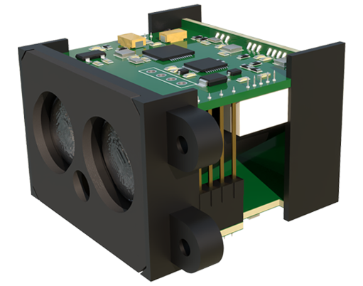
In industrial automation and precision engineering, achieving and maintaining surface parallelism is critical for ensuring product quality, operational efficiency, and system reliability. Laser sensors have emerged as a premier tool for this task, offering non-contact, high-speed, and highly accurate measurement capabilities. This article delves into the principles, methodologies, and best practices for using laser sensors to measure and verify surface parallelism.
The core principle behind laser-based parallelism measurement involves triangulation or time-of-flight techniques. A laser displacement sensor projects a focused beam onto a target surface. The reflected light is captured by a receiving element, such as a CCD or PSD. By analyzing the position or the phase shift of the reflected spot, the sensor calculates the precise distance to the point of incidence. To assess parallelism between two surfaces, multiple sensors are typically employed in a coordinated setup, or a single sensor is used to take sequential measurements at defined reference points across the surfaces in question.
A common configuration involves two or more laser displacement sensors fixed in a rigid frame or CMM (Coordinate Measuring Machine). Each sensor measures the distance to its corresponding point on the target surfaces. By comparing the distance readings from paired sensors—one for the reference surface (e.g., a machine bed) and one for the surface being inspected (e.g., a workpiece or moving stage)—the system can compute the angular deviation or tilt. This data directly indicates the degree of parallelism. Advanced systems integrate these sensors with software that provides real-time graphical feedback, statistical process control (SPC) charts, and pass/fail judgments against predefined tolerances.
Key factors influencing measurement accuracy include sensor selection, environmental stability, and proper alignment. For parallelism applications, choosing a sensor with appropriate resolution (often in the micron or sub-micron range), spot size, and measurement range is paramount. Environmental factors such as ambient light, temperature fluctuations, and vibrations can introduce noise; thus, operating in controlled conditions or using sensors with robust filtering algorithms is advisable. The initial alignment of the sensor system itself is crucial. The laser beams must be perpendicular to the nominal plane of the reference surface to avoid cosine error, which can skew distance readings and lead to incorrect parallelism calculations.
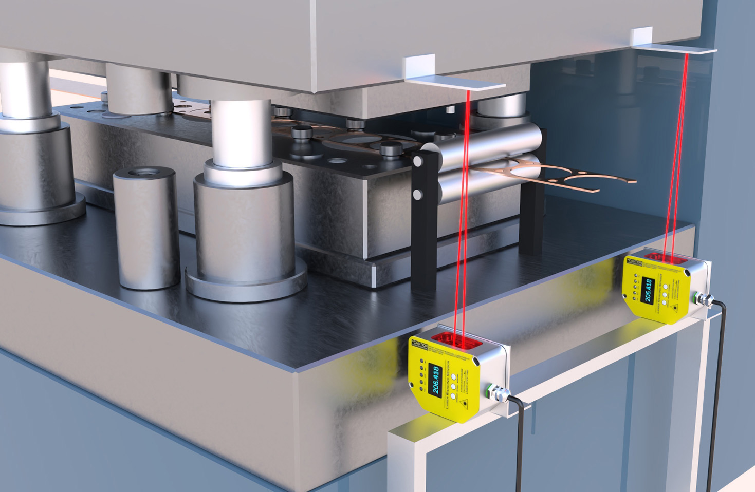
The process typically follows these steps: First, establish a stable mechanical reference. Second, perform a system calibration using a master artifact of known flatness and parallelism. Third, mount the sensors securely, ensuring their beams are properly oriented. Fourth, acquire measurement data from both surfaces under stable conditions. Finally, analyze the differential data. Non-parallelism may manifest as a consistent offset (indicating a fixed tilt) or a varying offset across the measurement length (indicating warping or curvature).
Applications are widespread across manufacturing. In semiconductor production, laser sensors ensure wafer stages are perfectly parallel to photolithography scanners. In automotive assembly, they verify the parallelism of engine block faces or brake disc mounting surfaces. In precision machining, they are used to align CNC machine tool axes and inspect finished parts. The non-contact nature of lasers prevents surface damage and allows measurement of delicate, hot, or moving objects where tactile probes would fail.
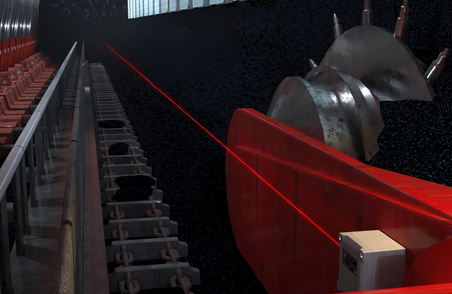
Despite their advantages, challenges exist. Highly reflective, transparent, or dark surfaces can scatter or absorb laser light, leading to measurement dropout or inaccuracy. Solutions include using sensors with adjustable laser power, employing specialized coatings on targets, or selecting sensors designed for difficult surfaces. Furthermore, the initial investment and expertise required for system integration can be higher than for traditional methods like dial indicators or feeler gauges. However, the long-term benefits in speed, repeatability, and data integration for Industry 4.0 systems often justify the cost.
In conclusion, laser sensors provide a powerful, flexible solution for demanding parallelism measurement tasks. By understanding their operating principles, carefully configuring the measurement system, and mitigating environmental and target-surface challenges, engineers can achieve unparalleled levels of precision and control in their manufacturing and quality assurance processes. As sensor technology continues to advance with features like blue lasers for better performance on organic materials and embedded Ethernet for seamless data communication, their role in ensuring geometric perfection will only expand.