Proximity sensors are essential components in modern automation systems, enabling contactless detection of objects within a specified range. Proper connection and transmission setup are critical for ensuring accurate and reliable operation. This guide provides a comprehensive overview of proximity sensor wiring, signal transmission methods, and practical implementation tips.
Understanding the basic types of proximity sensors is the first step. Inductive sensors detect metallic objects, capacitive sensors respond to both metallic and non-metallic materials, and photoelectric sensors use light beams for detection. Each type requires specific connection considerations based on its operating principle and output configuration.
Wiring proximity sensors typically involves three main components: power supply, load, and the sensor itself. Most industrial proximity sensors operate on DC voltages (10-30V DC) or AC voltages (90-250V AC). The connection diagram usually includes brown wire for positive voltage, blue wire for negative or neutral, and black wire for the output signal. For PNP (sourcing) sensors, the output provides positive voltage when activated, while NPN (sinking) sensors provide a path to ground. Proper identification of these configurations prevents damage to both sensors and connected equipment.
Transmission methods vary depending on application requirements. Digital outputs provide simple ON/OFF signals, ideal for basic detection tasks. Analog outputs offer continuous voltage or current signals proportional to detection distance, suitable for precision measurement applications. Some advanced sensors feature IO-Link communication, enabling digital data exchange including parameter settings, diagnostics, and process values through standard three-wire connections.
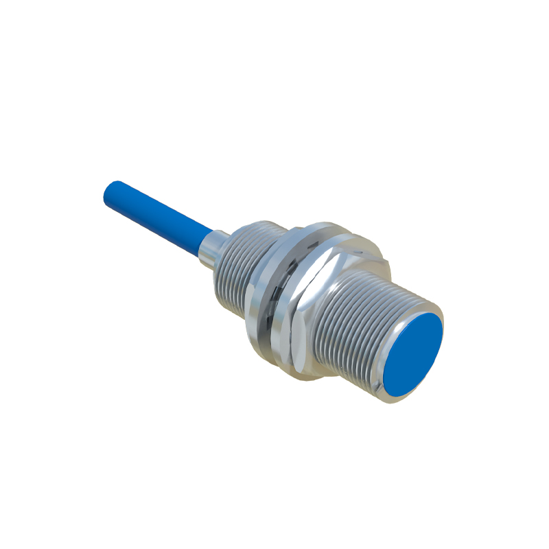
Shielded cables are recommended for installation in electrically noisy environments. The shielding should be grounded at only one end to prevent ground loops. Cable length considerations are important – excessive length can cause voltage drop and signal degradation. Generally, cables should not exceed 100 meters for analog signals and 300 meters for digital signals without proper amplification or signal conditioning.
Interfacing with programmable logic controllers (PLCs) requires attention to input compatibility. PNP sensors connect to PLC sinking inputs, while NPN sensors connect to sourcing inputs. Incorrect matching can result in malfunction or permanent damage. For analog sensors, ensure the PLC analog input module matches the sensor's output range (0-10V, 4-20mA, etc.). Many modern sensors offer programmable outputs that can be configured for different ranges and functions.
Environmental factors significantly impact transmission reliability. Temperature extremes can affect signal integrity, while moisture and corrosive substances may degrade connections over time. Proper sealing and enclosure selection based on IP (Ingress Protection) ratings ensure long-term performance. Sensors in high-vibration applications benefit from strain relief cable glands and secure mounting.
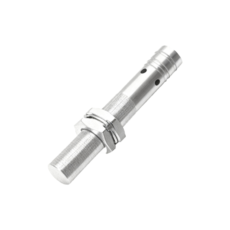
Diagnostic features in contemporary proximity sensors simplify troubleshooting. Many models include LED indicators showing power status and output activation. Smart sensors with IO-Link capability provide detailed diagnostic information including operating hours, temperature data, and signal quality metrics. Regular maintenance should include checking connection tightness, cable integrity, and sensor alignment.
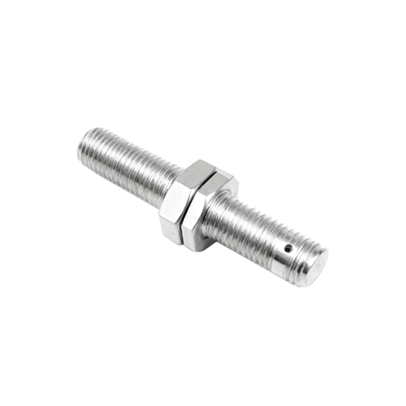
Wireless transmission options are increasingly available for challenging installation scenarios. These systems convert sensor signals to radio frequency transmissions, eliminating wiring constraints while maintaining reliable communication within specified ranges. Battery-powered wireless sensors offer flexibility but require periodic battery replacement considerations.
Safety considerations must never be overlooked. Always disconnect power before making connections. Follow lockout-tagout procedures in industrial settings. For safety-critical applications, use redundant sensors or safety-rated devices with appropriate safety relays or controllers. Emergency stop circuits should never rely solely on proximity sensor signals without proper safety validation.
Calibration and testing ensure optimal performance. After installation, verify the sensing distance under actual operating conditions with target materials. Adjust sensitivity settings if available, considering factors like target size, material, and approach speed. Document all settings for future reference and maintenance purposes.
Advancements in proximity sensor technology continue to improve connection and transmission capabilities. Self-teaching sensors automatically adjust to application conditions, while multi-functional devices combine detection with measurement and communication features. Integration with Industrial Internet of Things (IIoT) systems enables remote monitoring and predictive maintenance capabilities.
Proper installation practices combined with appropriate connection methods result in reliable object detection systems. Whether for simple presence detection or complex positioning applications, understanding proximity sensor connection and transmission principles ensures successful implementation across various industrial and commercial applications.