In industrial automation, the correct connection of sensors and proximity switches is fundamental to ensuring reliable system operation. Proximity switches, which detect the presence or absence of an object without physical contact, are widely used in applications such as material handling, assembly lines, and safety systems. This article provides a comprehensive guide on wiring and integrating these components, adhering to standard practices in electrical engineering.
First, it is essential to understand the types of proximity switches available. Inductive proximity switches detect metallic objects, while capacitive types can sense both metallic and non-metallic materials. Photoelectric sensors use light beams for detection, and ultrasonic sensors rely on sound waves. Each type has specific wiring requirements based on its operating principle and output configuration.
When connecting a proximity switch, start by identifying its specifications. Check the datasheet for voltage ratings (commonly 12-24V DC or 110-240V AC), output type (PNP or NNP for DC, or relay for AC), and current capacity. Ensure the power supply matches these parameters to prevent damage. For DC sensors, PNP (sourcing) outputs provide a positive voltage when activated, while NPN (sinking) outputs connect to ground. Incorrect wiring can lead to malfunction or short circuits.
Wiring typically involves three or four wires: power (brown or red), ground (blue or black), output (black or white), and sometimes a separate shield wire for noise reduction. Use shielded cables in environments with electromagnetic interference (EMI), such as near motors or frequency drives. Connect the shield to ground at one end only to avoid ground loops. Strip the wires carefully, secure them with appropriate terminals, and follow color-coding standards (e.g., IEC 60947-5-2) for consistency.
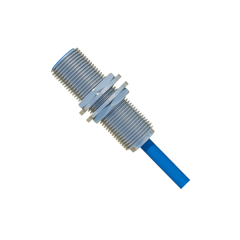
Integration with control systems like PLCs (Programmable Logic Controllers) requires attention to input compatibility. For a PNP sensor, connect its output to a PLC’s sinking input module; for NPN, use a sourcing input. Verify the PLC’s input voltage range matches the sensor’s signal. In relay-based systems, connect the output to the coil terminals, ensuring the load (e.g., a contactor or indicator) does not exceed the switch’s rating. Always install fuses or circuit breakers for overcurrent protection.
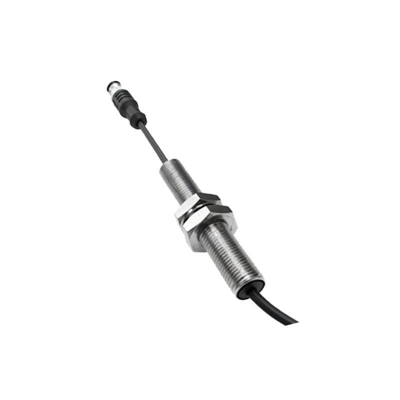
Testing is critical after installation. Use a multimeter to check voltage levels at the sensor output when an object is detected. Monitor for false triggers due to environmental factors like vibration, dust, or temperature extremes. Adjust the sensor’s sensitivity or hysteresis settings if available, and ensure proper mounting alignment. Regular maintenance, including cleaning lenses for photoelectric sensors or checking for metal debris on inductive types, prolongs component life.
In summary, successful sensor and proximity switch connections depend on accurate specification matching, adherence to wiring standards, and thorough testing. By following these guidelines, engineers can enhance system reliability, reduce downtime, and improve safety in automated industrial environments.