Laser sensors are critical components in modern industrial automation, offering high precision for tasks like object detection, positioning, and measurement. As an electrical engineer, ensuring their optimal performance is paramount for system reliability. A systematic approach to checking and troubleshooting these devices can prevent costly downtime. This guide outlines a professional methodology.
1. Preliminary Visual and Environmental Inspection
Before applying power, conduct a thorough visual inspection. Check the sensor housing for any physical damage, cracks, or signs of impact. Ensure the lens is clean and free from dust, oil, or debris, as contamination is a leading cause of signal attenuation or false readings. Use only approved lens cleaning materials. Verify the installation: confirm the sensor is securely mounted, properly aligned with the target, and that mounting brackets haven't loosened due to vibration. Assess the environment for excessive ambient light, which can interfere with the sensor's receiver, and for conditions like high humidity, temperature extremes, or airborne particulates that may exceed the sensor's specified ingress protection (IP) rating.
2. Power Supply and Electrical Connection Verification
Incorrect power is a common failure point. Confirm the power supply voltage matches the sensor's specifications (e.g., 10-30 VDC). Use a multimeter to measure the voltage at the sensor's terminals under load to rule out voltage drops from long cable runs or inadequate supply current. Check the wiring meticulously. For a 3-wire DC sensor, verify the correct connection of brown (positive), blue (negative/0V), and black (output) wires. For 4-wire models with dual outputs, confirm the wiring per the datasheet. Inspect cables for cuts, pinch points, and ensure connectors are fully seated and free from corrosion. A loose ground connection can cause erratic behavior.
3. Functional Testing and Parameter Configuration
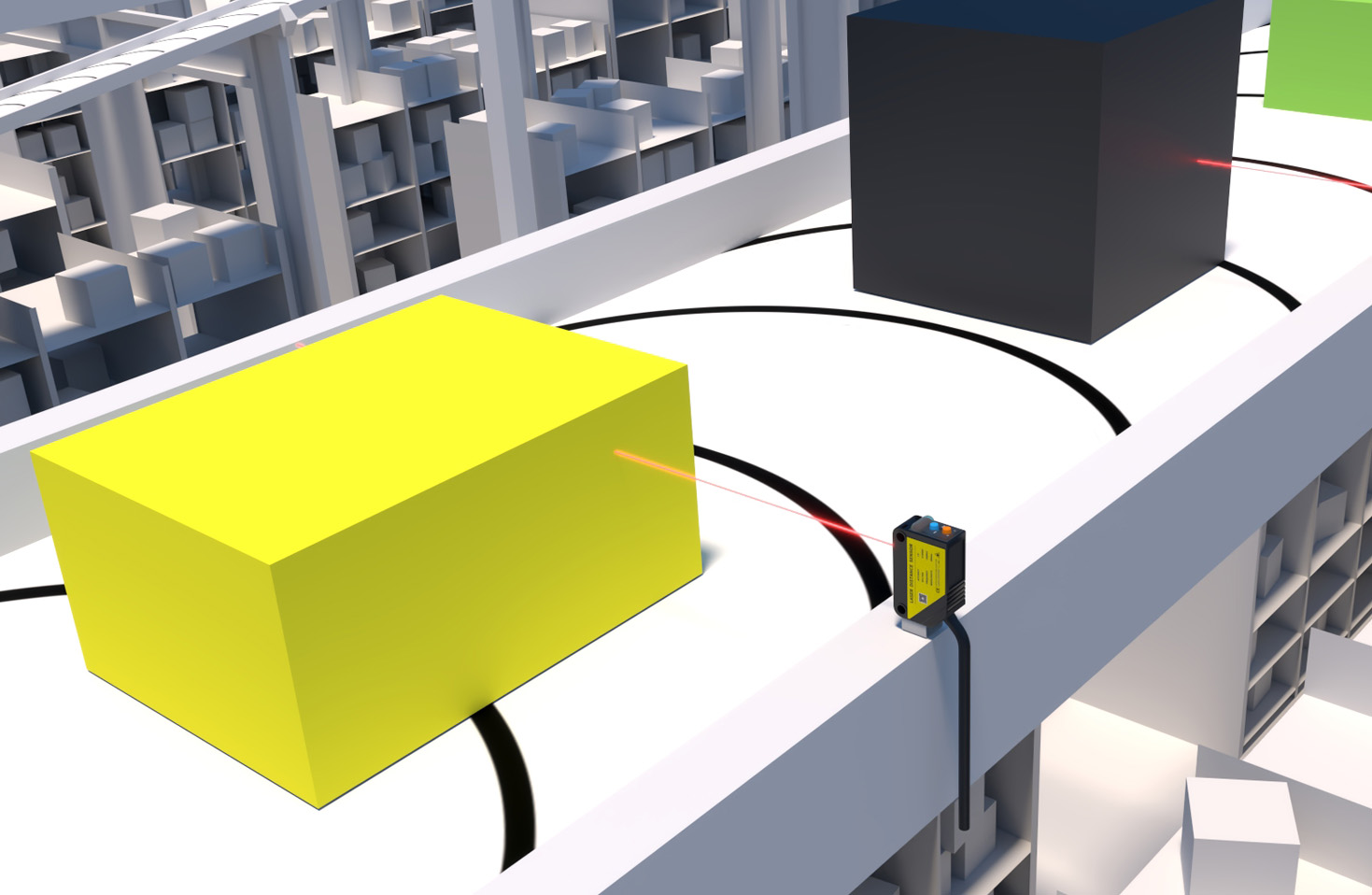
Power on the sensor. Most modern laser sensors have indicator LEDs (Power, Output, Stability). A steady power LED confirms basic functionality. Consult the manufacturer's manual to understand the LED status patterns. Next, verify the sensing mode (through-beam, retro-reflective, or diffuse reflective) is correctly applied for the application. Use the sensor's teach-in button or programming interface to set parameters like sensing distance, output delay, and switching hysteresis. For analog output sensors, measure the output current or voltage across the expected measurement range using a multimeter or oscilloscope to ensure it scales linearly. Test the digital output by introducing a target within the sensing range and confirming the output LED activates and the corresponding PLC input registers the change.

4. Advanced Diagnostics and Signal Analysis
If basic checks pass but performance issues persist, deeper diagnostics are needed. Oscilloscope Analysis: For sensors with a modulated laser beam, probe the output signal. A clean, stable square wave indicates proper operation. Noise, jitter, or an attenuated signal suggests interference or component issues. Response Time Test: Measure the time delay between the target entering the sensing field and the output switching. Compare it to the datasheet's specified response time. Slower response may indicate a failing component or incorrect filter settings. Background Suppression (BGS) Sensors: For diffuse sensors with BGS, test with objects at different distances to ensure the cutoff distance is stable and not influenced by the object's color or reflectivity. Light Spot Check: Use alignment cards or manufacturer-specific tools to visualize the laser spot. Ensure it is focused, circular, and correctly positioned. A distorted or dim spot can indicate a failing laser diode or lens misalignment.
5. Troubleshooting Common Faults
* No Output: Confirm power, wiring, and that the target is within the sensing range and of sufficient size/reflectivity. Check if the output is configured as NPN (sinking) or PNP (sourcing) to match the controller's input type.
* Intermittent or Unstable Output: This is often caused by electrical noise, vibration, or marginal sensing conditions. Ensure proper shielding of cables, separate sensor cables from power lines, and check grounding. Verify the target is consistently presented. Increase hysteresis or use a faster response filter if applicable.
* Inaccurate Measurements (for analog sensors): Re-calibrate using known distance standards. Check for temperature drift if the environment has changed. Ensure the target surface properties are consistent.
* Sensor Cannot be Taught: The target may be outside the teachable range, or the sensing conditions may be optically unfavorable (e.g., a transparent or highly absorbent target). Try a reference target with standard reflectivity.
6. Documentation and Preventive Maintenance
Always document your findings, adjustments made, and sensor parameters. Implement a preventive maintenance schedule that includes periodic lens cleaning, re-verification of alignment and mounting integrity, and functional spot-checks. Keep the sensor's original datasheet and manual accessible for reference.
A disciplined, step-by-step approach—from basic visual checks to advanced signal analysis—is the hallmark of effective laser sensor maintenance. Understanding the operating principle of your specific sensor model is crucial for interpreting its behavior and diagnosing non-obvious faults, thereby ensuring long-term system integrity and precision.