In the realm of industrial automation and electronic design, proximity sensor modules are indispensable components. Their ability to detect the presence or absence of an object without physical contact makes them critical for applications ranging from assembly line automation to consumer electronics. This article delves into the schematic design of these modules, providing a detailed analysis for electrical engineers seeking to understand, select, or design these systems.
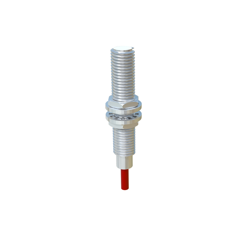
At its core, a proximity sensor module schematic can be broken down into three fundamental blocks: the sensing element, the signal conditioning circuit, and the output interface. The sensing element is the frontline component. Inductive sensors use a coil to generate an electromagnetic field, detecting metallic objects. Capacitive sensors utilize a capacitor plate to sense both metallic and non-metallic materials by changes in capacitance. Photoelectric sensors employ an LED or laser diode paired with a phototransistor or photodiode to detect interruptions or reflections of a light beam. The choice of sensing technology directly dictates the initial stage of the schematic.
Following the sensor, the raw signal is weak and noisy. This is where the signal conditioning circuit comes into play. For inductive and capacitive sensors, this typically involves an oscillator circuit whose frequency or amplitude is perturbed by the target object. This change must be converted into a usable DC voltage. A common approach is to use a demodulator, filter, and amplifier stage. Operational amplifiers (op-amps) configured as comparators or amplifiers are ubiquitous here. The filtered signal is compared against a reference voltage, set by a potentiometer to adjust sensitivity, to create a clean digital transition. For photoelectric sensors, the photodetector's current output is converted to a voltage, often through a transimpedance amplifier, before being amplified and compared.
The final block is the output interface. This defines how the module communicates the detection event to a controller like a PLC, microcontroller, or relay. The two primary types are digital output and analog output. Digital output schematics are simpler, often featuring an open-collector NPN or PNP transistor. When the comparator triggers, the transistor switches, either sinking or sourcing current to provide a clean logic-high or logic-low signal. Protection components like flyback diodes for inductive loads and current-limiting resistors are crucial in this section. Analog output modules, less common but valuable for distance proportionality, might use a voltage follower or a dedicated voltage/current output IC to provide a 0-10V or 4-20mA signal corresponding to the target's distance.
Power supply design is another critical aspect integrated into the schematic. Most modules operate on a wide DC range (e.g., 10-30V DC). A voltage regulator, such as a 78L05, is standard to provide a stable +5V rail for the ICs and oscillator. Decoupling capacitors placed near each active component are non-negotiable for stability, filtering high-frequency noise from the power lines.
When analyzing or creating a schematic, engineers must pay close attention to several key parameters. The sensing range, clearly influenced by the coil/oscillator design or LED intensity, is paramount. Response time is determined by the filter time constants and comparator speed. Environmental robustness is achieved by incorporating protection against reverse polarity, short-circuits, and voltage spikes using diodes and fuses. For inductive sensors, a hysteresis circuit is often added around the comparator to prevent output oscillation when a target is at the exact threshold distance.
Modern advancements are also reflected in schematics. Integration has led to specialized ICs that combine the oscillator, demodulator, and comparator in a single package, simplifying design. Some modules now include diagnostic LEDs and digital communication interfaces like IO-Link, which require additional circuitry for serial communication.
In conclusion, a proximity sensor module schematic is a elegant synthesis of analog and digital electronics. Understanding each block—the sensor physics, the conditioning circuitry's role in noise immunity, and the robust output stage—is essential. Whether for troubleshooting, customization, or original design, a deep schematic analysis empowers engineers to deploy these modules effectively, ensuring reliability and precision in the most demanding automated environments.