In industrial automation and electrical control systems, proximity switches are critical components for detecting the presence or absence of objects without physical contact. Proper installation, including the correct use of shims, is essential to ensure reliable operation, accuracy, and longevity. This guide provides a detailed overview of proximity switch sensor shim installation, focusing on best practices for electrical engineers and technicians.
Shims, often thin metal or non-metallic spacers, are used to adjust the sensing distance between the proximity switch and the target object. This adjustment is crucial because proximity switches have a specified sensing range, and deviations can lead to false triggers, missed detections, or reduced sensor life. The installation process begins with selecting the appropriate shim material and thickness based on the sensor specifications and environmental conditions. Common materials include stainless steel for durability in harsh environments and plastic or fiber for non-metallic applications to avoid interference.
Before installation, ensure the power supply is disconnected to prevent electrical hazards. Mount the proximity switch in its designated location using the provided brackets or fixtures. Check the manufacturer’s datasheet for the recommended gap between the sensor face and the target. If the initial gap is too large or small, measure the discrepancy and choose a shim that compensates for it. For example, if the gap exceeds the maximum sensing distance by 2 mm, a 2 mm shim can be inserted behind the sensor to bring it closer to the target.
To install the shim, loosen the mounting screws slightly without removing them completely. Slide the shim between the sensor and the mounting surface, ensuring it is flat and aligned to avoid tilting. Tighten the screws evenly to secure the sensor and shim in place, applying the torque specified by the manufacturer to prevent damage. After installation, verify the alignment by checking that the sensor face is parallel to the target surface. Misalignment can cause inconsistent readings, so use a level or alignment tool if necessary.
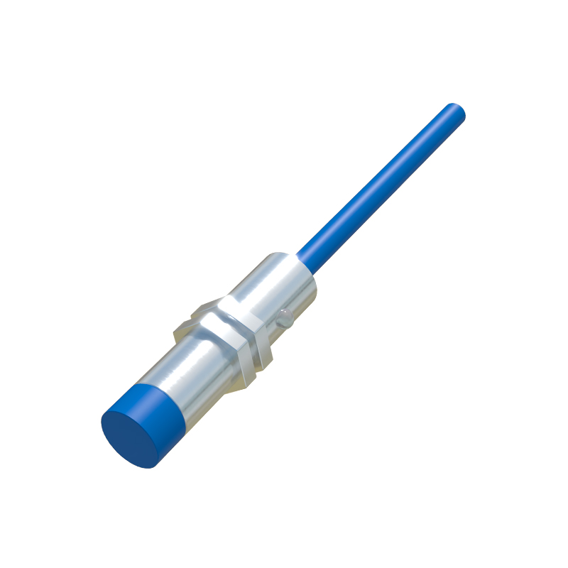
Once the shim is installed, reconnect the power and test the sensor’s functionality. Use a target object that matches the sensor’s specifications (e.g., material and size) to verify the sensing distance. Adjust the shim thickness if the sensor does not trigger reliably—this may involve trial and error with different shim sizes. In applications with multiple proximity switches, ensure consistency by using identical shims for all sensors to maintain uniform performance.
Environmental factors must also be considered during shim installation. In high-vibration settings, use locking washers or thread-locking compounds on the screws to prevent loosening. For corrosive environments, select shims made from resistant materials like galvanized steel or coated plastics. Additionally, avoid placing shims in areas with extreme temperatures that could cause expansion or contraction, affecting the gap over time.
Regular maintenance is key to long-term reliability. Periodically inspect the shims and sensors for signs of wear, corrosion, or loosening. Clean the sensor face and shim surfaces to remove dust, oil, or debris that could interfere with detection. If adjustments are needed, repeat the installation steps carefully, and document any changes for future reference.
In summary, proper shim installation for proximity switches involves precise measurement, material selection, and alignment. By following these guidelines, electrical professionals can optimize sensor performance, reduce downtime, and enhance system safety. Always refer to the sensor manufacturer’s instructions for specific details, as requirements may vary by model and application.