Hall effect proximity sensors are critical components in modern industrial automation, motion control, and safety systems. They detect the presence or absence of a magnetic field, typically from a moving target like a gear tooth or a magnet, and provide a corresponding digital or analog output signal. A malfunctioning sensor can lead to equipment downtime, process errors, or even safety hazards. Therefore, knowing how to systematically check a Hall effect sensor is an essential skill for maintenance technicians and engineers. This guide outlines a practical, step-by-step methodology for verifying sensor health.
Before beginning any testing, ensure all safety protocols are followed. Disconnect power to the sensor's circuit whenever possible. If live testing is necessary, use appropriate personal protective equipment (PPE) and insulated tools. Gather the necessary equipment: a digital multimeter (DMM), an oscilloscope (for advanced analysis), the sensor's datasheet, a known-good magnet or the target it is designed to detect, and any necessary wiring or connectors.
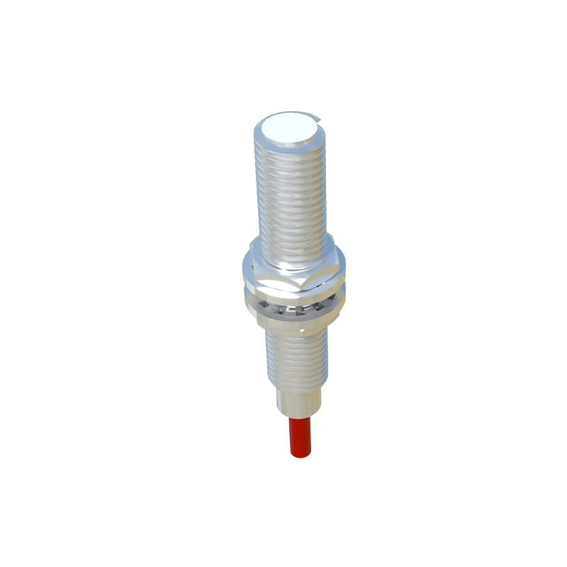
Step 1: Visual and Physical Inspection
Start with a thorough visual examination. Look for obvious signs of damage such as cracks in the sensor housing, bent or corroded pins, or melted plastic from overheating. Check the cable and connector for cuts, abrasions, or loose terminals. Ensure the sensor is mounted securely and correctly aligned with its target. Physical damage often indicates internal failure.
Step 2: Verify Power Supply and Wiring
Refer to the sensor's datasheet to confirm its voltage requirements (commonly 5V DC, 12V DC, or 24V DC). With power disconnected, use the multimeter in continuity mode to check the wiring from the power source to the sensor connector for any open or short circuits. Reconnect power and carefully measure the voltage between the V+ (supply) and V- (ground) pins at the sensor's terminals. The reading must be within the specified tolerance (e.g., 24V ±10%). An incorrect supply voltage is a common cause of sensor failure.
Step 3: Check the Output Signal (Static Test)
With the datasheet in hand, identify the output pin configuration (PNP/NPN, normally open/closed). For a simple static test, set your multimeter to the appropriate DC voltage scale. For a digital (switching) sensor, measure the output voltage relative to ground. In the absence of the target (magnetic field), the output should be in its default state (e.g., high ~24V for a PNP NO, or low ~0V for a PNP NC). Then, introduce the target magnet to the sensor's active face. The output state should switch. For example, a PNP Normally Open (NO) sensor's output should jump from ~0V to near the supply voltage when the magnet is presented. The absence of this voltage swing indicates a problem.
Step 4: Check the Output Signal (Dynamic Test with Oscilloscope)
For sensors used in high-speed applications (e.g., speed sensing on a motor shaft), a dynamic test is superior. Connect the oscilloscope probe to the output signal line. Manually or mechanically move the target magnet repeatedly past the sensor face. You should observe a clean, square-wave signal switching between the defined high and low voltages. Check for signal integrity: the rise and fall times should be sharp, with no excessive noise, ringing, or dropouts. A distorted or inconsistent waveform suggests internal component degradation or electrical interference.
Step 5: Measure Output Current (If Applicable)
Some sensors are designed to sink or source a specific current. Using the multimeter in current measurement mode (in series with the load), verify that the output current under load matches the datasheet specifications when the sensor is activated. An output that cannot drive its rated load may be failing.
Step 6: Environmental and Sensitivity Checks
Consider the operating environment. Excessive heat, vibration, or exposure to strong external magnetic fields can cause intermittent faults or calibration drift. If possible, test the sensor's sensing distance with the specified target. A significant reduction in the nominal sensing range may indicate a weak internal Hall element or damaged amplifier circuit.
Interpretation of Results and Troubleshooting:
No Output Change: If the supply voltage is correct but the output remains static regardless of the magnet's presence, the sensor is likely defective. Double-check wiring and the magnet's strength/orientation first.
Intermittent Output: This often points to a loose connection, damaged cable, or internal cold solder joint. Wiggle the wires and connector while monitoring the output.
Incorrect Output Voltage Level: An output that does not reach the full supply voltage (e.g., only reaching 15V on a 24V system) may indicate a failing output transistor or excessive internal resistance