In industrial automation, laser line tracking sensors are critical components for precision guidance, measurement, and inspection tasks. Their ability to project a sharp, visible line onto a target surface and analyze the reflected pattern enables applications ranging from robotic path following and weld seam tracking to edge detection and 3D profiling. However, achieving consistent, reliable performance requires meticulous calibration and a systematic approach to troubleshooting. This guide outlines key procedures and best practices for engineers.
The initial setup begins with mechanical and optical alignment. Ensure the sensor is securely mounted with minimal vibration. The projection angle and working distance must adhere to the manufacturer's specifications. A common mistake is operating outside the sensor's optimal range, leading to poor line clarity or insufficient reflection. The projected laser line should be crisp, continuous, and perpendicular to the direction of travel or measurement on the target surface. For curved or uneven surfaces, this may require iterative adjustment.
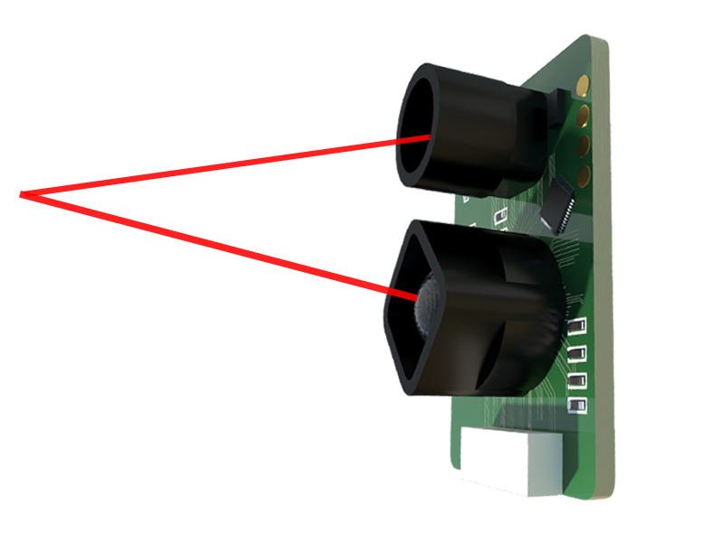
Next, focus on the environmental factors. Ambient light is a primary adversary. Strong overhead lighting or sunlight can wash out the laser line. Whenever possible, employ physical shrouding or install the sensor in an enclosure. Alternatively, many modern sensors allow adjustment of the laser power or utilize narrow-band optical filters matched to the laser's wavelength to suppress ambient noise. The surface characteristics of the target are equally crucial. Highly reflective, glossy, or transparent materials can cause specular reflection or scatter, distorting the line image. Conversely, dark, matte, or absorptive surfaces may return too weak a signal. For challenging surfaces, techniques like applying a temporary matte coating, adjusting the incidence angle, or using a sensor with automatic exposure control can be effective.
Calibration is a multi-step software process within the sensor's configuration interface or paired PLC/software. First, establish a baseline reference. This often involves teaching the sensor the "background" or a known good state without the target present. Then, introduce a standard calibration target or the actual workpiece. Key parameters to adjust include:
1. Exposure/Gain: Controls the camera's sensitivity. Adjust until the line is bright and clear without blooming (saturation) or being too faint.
2. Threshold: Sets the intensity level to distinguish the laser line from the background. An adaptive threshold is preferable for variable conditions.
3. Region of Interest (ROI): Define the specific area within the camera's field of view where the line is expected. This reduces processing time and eliminates irrelevant data.
4. Filtering Parameters: Apply algorithms to smooth the detected line, reject outliers (noise pixels), and interpolate gaps in the line.
5. Measurement Origin/Offset: Define the coordinate system so the sensor's output (e.g., position deviation in mm) is referenced correctly to the machine's datum.
Always validate calibration by running the process with multiple samples that represent the full range of acceptable product variation. Document the final parameter set.
When performance degrades, a structured troubleshooting methodology is essential. Start with the simplest checks:
* Visual Inspection: Is the laser line visibly bright and straight? Is the lens clean and free of dust, oil, or debris?
* Power & Connections: Verify all electrical connections and communication cables (Ethernet, IO-Link, etc.) are secure. Check for stable power supply voltage.
* Review Raw Image: Most advanced sensors provide a software tool to view the raw camera image. This is invaluable. Observe if the line is broken, distorted, or has competing reflections.
If the issue persists, analyze symptom patterns:
* Inconsistent Measurements: Often caused by varying surface reflectivity, ambient light changes, or mechanical looseness. Revisit environmental controls and mechanical mounting. Consider enabling averaging or filtering in the sensor's output.
* Complete Loss of Signal: Could indicate laser diode failure, severe misalignment, or a heavily contaminated lens. Check laser safety status indicators if available.
* Erratic or Noisy Data: Frequently stems from electrical interference, ground loops, or insufficient shielding of cables. Ensure proper grounding practices are followed and separate sensor cables from high-power lines.
* Communication Failures: Verify network settings, baud rates, and protocol configuration. Check for IP address conflicts in networked systems.
For complex systems, remember the sensor is part of a larger chain. Verify the logic in the PLC or controller interpreting the sensor's data. A mismatch in data scaling or update rates can cause issues that appear sensor-related.
Proactive maintenance is key to long-term reliability. Establish a schedule for cleaning optics with approved materials, checking mounting integrity, and re-validating calibration against a master reference part, especially after any mechanical maintenance on the host machine. By mastering calibration fundamentals and adopting a logical troubleshooting flow, engineers can ensure their laser line tracking sensors deliver the high accuracy and robustness demanded in modern automated environments.