In the realm of industrial automation and precision metrology, laser displacement sensors are indispensable tools for non-contact measurement of distance, thickness, and vibration. However, the accuracy and repeatability of these high-performance sensors are only as good as the fixtures and jigs that hold and calibrate them. A well-engineered sensor jig is not merely a bracket; it is a critical subsystem that ensures measurement integrity, mitigates environmental variables, and maximizes operational efficiency. This article delves into the design principles, material considerations, and application-specific configurations of professional-grade jigs for laser displacement sensors.
The primary function of a laser displacement sensor jig is to provide a rigid, stable, and precisely adjustable mounting platform. Vibration, thermal drift, and mechanical deflection are the archenemies of micron-level accuracy. Therefore, jig design begins with structural rigidity. Materials like aluminum alloys (e.g., 6061-T6) are favored for their excellent strength-to-weight ratio and good machinability. For applications in thermally volatile environments or requiring ultimate stability, stainless steel or invar alloys are employed, albeit at a higher cost and weight. The design must counteract all potential forces—from the weight of the sensor itself to cable drag and incidental contact—ensuring the sensor's optical axis remains unwavering relative to the target.
Adjustability is the second cornerstone. A high-quality jig incorporates fine-adjustment mechanisms for at least five degrees of freedom: three linear (X, Y, Z) and two angular (pitch and yaw). Micrometer heads, precision lead screws, or goniometric stages are integrated to allow for meticulous alignment. This is crucial during initial setup and for compensating for long-term drift or when switching sensor models. The adjustment mechanisms must be backlash-free and lockable once the optimal position is achieved. A common best practice is to design a "kinematic mount" principle, which allows for precise, repeatable positioning and secure locking without inducing stress that could deform the jig.
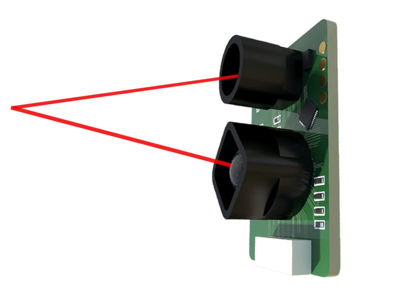
Beyond holding the sensor, advanced jigs incorporate features for in-situ calibration and verification. This may include integrated reference artifacts, such as a high-grade gauge block or a mirror-flat surface at a known distance, allowing operators to perform quick sanity checks against a traceable standard without removing the sensor from the line. Some jigs also feature environmental shielding, with shrouds or enclosures to protect the sensor's lens from dust, oil mist, or stray ambient light, which can interfere with the laser triangulation or time-of-flight measurement principles.
The integration of the jig into the larger automation system is a critical phase. Factors such as cable management routes, connector accessibility for maintenance, and compatibility with existing machine frames (e.g., T-slotted aluminum extrusions, ISO standard mounting patterns) must be meticulously planned. A poorly routed cable can exert a tiny but significant torque on the sensor head, leading to drift. Modern designs often include dedicated channels or strain relief systems to isolate the sensor from such influences.
In application, the configuration of the jig varies significantly. For example, a jig used in roll gap measurement in steel mills must withstand extreme temperatures and vibration, often requiring water-cooling channels within the jig body. Conversely, a jig for measuring PCB flatness in electronics assembly might prioritize rapid tool-less adjustment for high-mix production lines. In robotic guidance systems, the jig must be ultra-lightweight yet stiff to not burden the robot's payload capacity, often utilizing composite materials.
The return on investment from a professionally designed and fabricated sensor jig is substantial. It reduces setup time from hours to minutes, slashes measurement variability, decreases sensor damage from improvised mounting, and extends calibration intervals. It transforms the sensor from a sensitive instrument into a robust, production-ready measurement node.
Ultimately, the laser displacement sensor jig is a testament to the principle that in precision engineering, the interface between the tool and the world is paramount. Neglecting this interface undermines the capability of even the most advanced sensor. By investing in purpose-built, precision jigging, engineers ensure that their measurement systems deliver not just data, but trustworthy, actionable information that drives quality and efficiency in automated manufacturing processes.