Inductive proximity sensors are pivotal components in industrial automation, offering non-contact detection of metallic objects. This article delves into the operational principles, key features, and practical applications of these sensors, supported by illustrative images to enhance comprehension.
At their core, inductive proximity sensors generate an electromagnetic field via a coil and oscillator circuit. When a metallic target enters this field, eddy currents are induced, causing a change in oscillation amplitude. This alteration is detected by the sensor's circuitry, triggering an output signal—typically a switch to control external devices like relays or PLCs. Images depicting this process often show cross-sectional views of the sensor, highlighting the coil, oscillator, and detection zone, which help users visualize how the electromagnetic field interacts with targets.
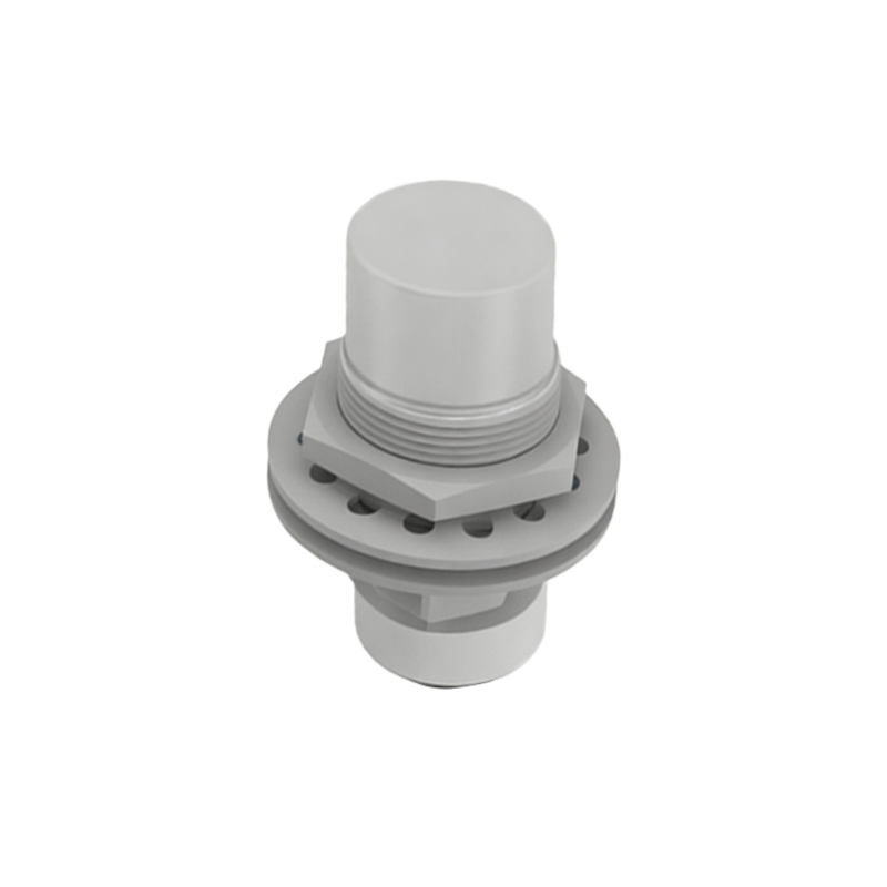
Key characteristics include sensing range, response frequency, and housing materials. Sensing range varies based on sensor size and target material, with standardized reduction factors for non-ferrous metals like aluminum or copper. For instance, a sensor with a 10mm range for steel might only detect aluminum at 5mm. Diagrams often compare these ranges using side-by-side illustrations, emphasizing the importance of material selection. Response frequency, measured in Hertz, indicates how quickly the sensor can detect objects—critical for high-speed automation lines. Visual charts in technical manuals plot frequency against distance, aiding in optimal sensor placement.
Housing designs, such as cylindrical, rectangular, or ring-shaped, cater to diverse installation needs. Cylindrical sensors, commonly used in machinery, feature threaded barrels for easy mounting, while rectangular variants suit conveyor systems. Ring sensors, ideal for detecting small parts, wrap around objects without physical contact. Photographs of these housings in real-world setups—like a cylindrical sensor monitoring piston movement in an assembly line—demonstrate their versatility.
Wiring configurations are another vital aspect. Two-wire sensors simplify installation but may have lower switching capacity, whereas three-wire versions (PNP or NPN) offer enhanced performance. Wiring diagrams, often color-coded, show connections to power supplies and loads, reducing installation errors. For example, a typical image might depict a brown wire for positive voltage, blue for negative, and black for the output signal, aligned with international standards like IEC 60947-5-2.
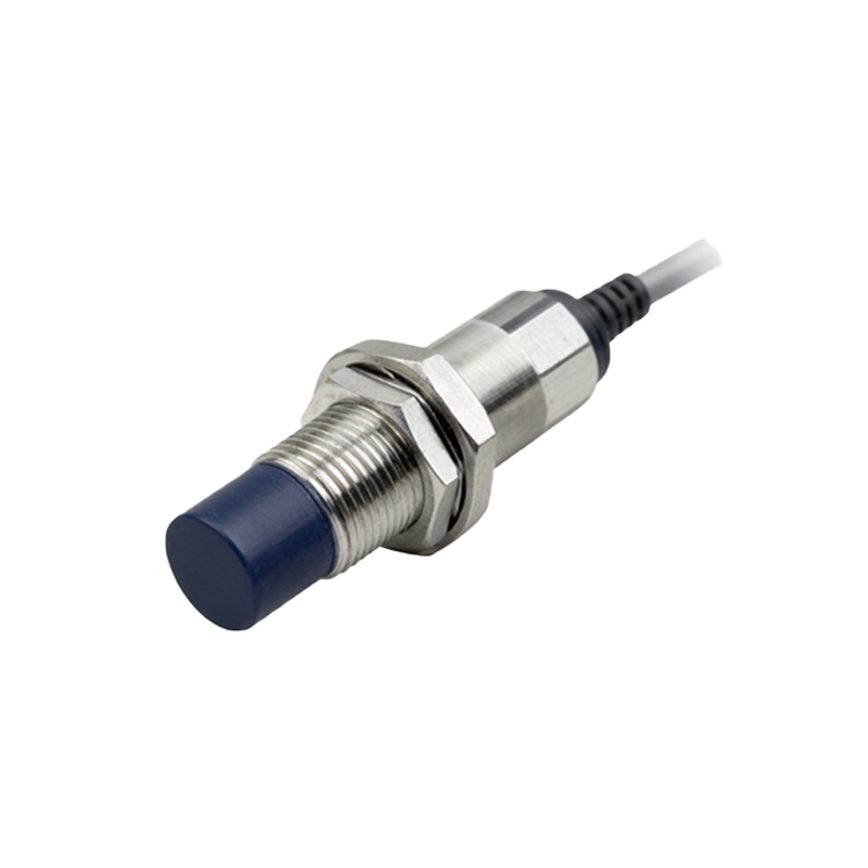
Applications span from manufacturing to robotics. In automotive plants, inductive sensors detect metal components on assembly belts, ensuring precise positioning. Images from such environments show sensors mounted near robotic arms, triggering actions when parts arrive. In packaging, they count metallic items on conveyors, with visual guides highlighting alignment angles to avoid false triggers. Safety systems also utilize them to monitor guard positions—photos often illustrate sensors attached to machine doors, cutting power if opened during operation.
Maintenance and troubleshooting benefit greatly from visual aids. Common issues include sensing range drift due to environmental factors like temperature or contamination. Step-by-step images in manuals guide technicians through calibration using target plates, ensuring accuracy. For instance, a series of pictures might show adjusting a potentiometer while measuring output with a multimeter. Additionally, LED indicators on sensors provide status feedback; close-up photos explain blinking patterns for diagnostics, such as continuous light indicating power-on or flashes signaling target detection.
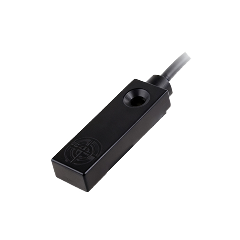
Advancements in technology have led to miniaturized and intelligent sensors. Modern variants integrate IO-Link communication for real-time data exchange, enabling predictive maintenance. Illustrations compare traditional sensors with smart versions, showcasing added ports for digital connectivity. In harsh conditions, like welding zones, specialized models with rugged housings resist spatter and EMI—images here emphasize protective coatings and shielding.
In summary, inductive proximity sensors are indispensable for efficient automation. Through detailed images—from cutaway diagrams to application snapshots—users gain a deeper understanding of their functionality and deployment. These visual tools not only aid in selection and installation but also enhance reliability in demanding industrial settings. Always refer to manufacturer guidelines and imagery for specific models to maximize performance.