Metallic proximity sensors are indispensable components in modern industrial automation, providing non-contact detection of metal objects. Their reliability is crucial for maintaining continuous production lines, but like all electronic devices, they are susceptible to failure. Understanding common failure modes and mastering repair techniques can significantly reduce downtime and operational costs. This guide outlines a systematic approach to diagnosing and repairing these sensors, adhering to industry best practices.
The first step in any repair process is accurate diagnosis. Common symptoms of a malfunctioning metallic proximity sensor include intermittent detection, complete failure to detect, erratic output signals, or physical damage to the housing. Before disassembly, always ensure the sensor is disconnected from its power source to prevent electrical shock or damage. Begin with a visual inspection. Check the sensor face for accumulation of metal chips, dirt, or coolant, as contaminants can attenuate the electromagnetic field. Inspect the housing for cracks, dents, or signs of impact. Examine the cable entry point and the cable itself for cuts, abrasions, or pinch points, which are frequent failure points due to mechanical stress.
Next, proceed with electrical testing using a multimeter. Verify the supply voltage at the sensor's terminals to ensure it matches the rated voltage (e.g., 10-30 VDC for many models). An incorrect supply voltage can cause malfunction. For a 3-wire DC sensor, measure the voltage between the brown (positive) and blue (negative) wires. Then, test the output. In a normally open (NO) configuration, the output wire (typically black) should show near supply voltage when no target is present and drop to near 0V when a valid metal target is within the sensing range. Failure to switch indicates an internal fault. For inductive sensors, you can use a metal screwdriver or a designated test target to simulate a metal object. Also, check for current draw; an abnormally high or low current can indicate a short circuit or an open circuit within the sensor's oscillator or amplifier stages.
If electrical tests point to an internal fault, careful disassembly is required. Many industrial sensors are potted with epoxy resin to protect the internal circuitry from moisture, vibration, and chemicals. Repairing a potted sensor is often impractical; replacement is usually more cost-effective. However, some modular or older models allow access to internal components. Upon opening the housing, inspect the core components: the oscillator coil, the ferrite core, the evaluation circuit board, and the output switching element (often a transistor or a relay).
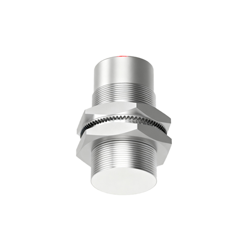
The oscillator coil is the heart of an inductive proximity sensor. Look for physical damage, loose windings, or discoloration from overheating. A broken coil wire will cause complete failure. You can test the coil's continuity and resistance with a multimeter, comparing the reading to the manufacturer's specifications if available. A significant deviation indicates a faulty coil. Replacing a coil requires careful soldering and ensuring the new coil's inductance matches the original to maintain the correct sensing characteristics.
The evaluation electronics on the circuit board are the next area of focus. Look for burnt components, cracked solder joints, or corroded traces, especially if there was evidence of moisture ingress. Capacitors, particularly electrolytic ones, are prone to failure over time and under high-temperature conditions. They may bulge or leak electrolyte. Test semiconductors like diodes and the output transistor. A common failure is a shorted output transistor due to overcurrent from an inductive load without proper protection. Replacing these components with correct, industry-grade equivalents is essential. After replacing any components, clean the board with isopropyl alcohol to remove flux residue or contaminants.
Reassembly is critical. Ensure all seals, O-rings, and gaskets are intact and properly seated to restore the sensor's IP (Ingress Protection) rating. Apply the correct thread sealant or tape if the sensor has a threaded barrel. Before final closure, perform a functional test. Reconnect the sensor to power and use a target to verify the sensing range and output switching. The sensing range should be consistent and close to the manufacturer's specification. Drift in sensing distance can sometimes be adjusted via a potentiometer on some sensor models, but this is not common in standard units.
Preventive maintenance is key to avoiding frequent repairs. Implement regular cleaning schedules to keep sensor faces free of debris. Use protective guards or brackets to shield sensors from physical impact. Ensure proper electrical installation, including correct wire sizing, secure connections, and the use of surge suppressors or flyback diodes when switching inductive loads. Adhering to the sensor's environmental specifications regarding temperature, humidity, and chemical exposure will greatly extend its service life.
In conclusion, while metallic proximity sensors are robust, they are not infallible. A methodical approach involving visual inspection, electrical diagnosis, and careful component-level repair can restore many units to service. However, engineers must weigh the time and cost of repair against