Accurate wiring is the cornerstone of reliable laser position sensor operation. As an electrical engineer, ensuring a correct and robust connection is paramount to achieving the precision measurements these devices are known for. This guide provides a detailed, step-by-step approach to wiring a typical industrial laser displacement sensor, focusing on common configurations and critical considerations.
First and foremost, consult the specific datasheet for your sensor model. While general principles apply, pinouts, voltage requirements, and communication protocols (e.g., analog voltage/current, RS-422, Ethernet/IP, PROFINET) vary significantly between manufacturers like Keyence, Panasonic, or SICK. Assume nothing from a generic diagram.
For a standard DC-powered sensor with a digital (NPN/PNP) or analog output, the process typically involves the following steps:
1. Power Supply Connection:

Identify the power terminals, usually labeled as V+ (or Vcc) and V- (or 0V). A stable, regulated DC power supply is essential. Common voltages are 12-24 VDC. Connect the positive lead from your power supply to the V+ terminal and the negative lead to the V- terminal. Implement appropriate fuse protection on the positive line as per the sensor's specifications. Noise from the power line is a frequent source of error; using a separate, clean power supply for sensitive measurement sensors is highly recommended over sharing with motors or solenoids.
2. Output Signal Connection:
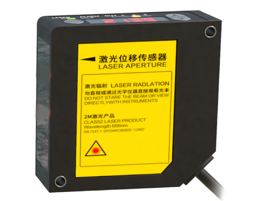
The output type dictates the wiring. For a Digital (Switching) Output (often NPN open collector or PNP):
* NPN Type: The output acts as a sink. The load (e.g., PLC input, relay) is connected between the sensor's output terminal and the positive supply voltage (+V). When active, the sensor sinks current to 0V.
* PNP Type: The output acts as a source. The load is connected between the sensor's output terminal and 0V. When active, the sensor sources current from +V.
Always verify the maximum load current the sensor output can handle.
For an Analog Output (e.g., 0-10V, 4-20mA):
* Connect the sensor's analog output wire to your controller's analog input channel.
* For voltage output, ensure a high-impedance input on the receiver.
* For current output (4-20mA is prevalent for its noise immunity), the loop must be completed by connecting the return wire to the controller's input and ensuring proper loop power configuration (often the controller provides the loop power).
3. Grounding and Shielding:
This is non-negotiable for signal integrity. Use a shielded, twisted-pair cable for all signal lines (analog outputs, communication lines). Connect the cable shield to a stable earth ground at *one end only*, typically at the controller or system ground point, to prevent ground loops. The drain wire should not be used as a signal conductor. Ensure the sensor housing is properly grounded if specified.
4. Control Line Connections (if applicable):
Many sensors feature control inputs for functions like external teach (latch), output enable, or reset. These are typically digital inputs to the sensor. Wire them according to the logic required (sink or source) and the sensor's internal circuitry, often requiring a connection to 0V or +V via a switch or PLC output.
5. Communication Interface Wiring:
For sensors with serial (RS-422/485) or network interfaces, follow the standard pinouts meticulously. For RS-422, you will connect TX+, TX-, RX+, RX- pairs. Use proper termination resistors (often 120Ω) at the end of the line for multi-drop configurations. For Ethernet-based sensors, use CAT5e or better cabling with RJ45 connectors, observing standard TIA-568A/B wiring.
Critical Safety and Performance Checks:
* Power Off: Always wire with the power supply disconnected.
* Polarity: Double-check polarity before applying power. Reverse polarity can cause permanent damage.
* Cable Routing: Route sensor cables away from high-voltage AC lines, motor drives, and welding equipment. Cross power cables at right angles if they must be near.
* Secure Connections: Use crimp ferrules on stranded wires for screw terminals to prevent fraying and ensure a gas-tight connection.
* Initial Power-Up: After wiring, apply power and observe the sensor's indicator LEDs. Most have a power/status LED and an output activation LED. Consult the manual for status codes.
* Signal Verification: Use a multimeter or oscilloscope to verify the output signal matches expected behavior when measuring a known target.
In summary, successful laser sensor wiring hinges on meticulous planning, adherence to the manufacturer's documentation, and rigorous attention to grounding and noise suppression. A correctly wired sensor is the first and most critical step in deploying a stable, high-accuracy measurement system. Invest time in the installation to avoid costly troubleshooting and downtime later.