Proximity speed sensors are fundamental components in modern industrial automation and machinery monitoring systems. These devices, often referred to as proximity switches or non-contact speed sensors, are engineered to detect the presence, absence, or rotational speed of a target object without any physical contact. Their operation hinges on the principle of electromagnetic induction or capacitive/inductive field disturbance, providing a reliable and wear-free method for speed measurement and position sensing in demanding environments.
The most common type used for speed sensing is the inductive proximity sensor. At its core, it consists of an oscillator circuit that generates a high-frequency electromagnetic field emanating from the sensor's active face. This field is typically stable when no metallic target is within its detection range. When a ferrous or non-ferrous metallic target, such as a gear tooth, keyway, or bolt head, approaches this field, eddy currents are induced on the surface of the target. These eddy currents draw energy from the oscillator, causing a measurable change in its amplitude or frequency. An internal signal conditioning circuit detects this change and triggers a solid-state switch, producing a clean, digital output pulse.
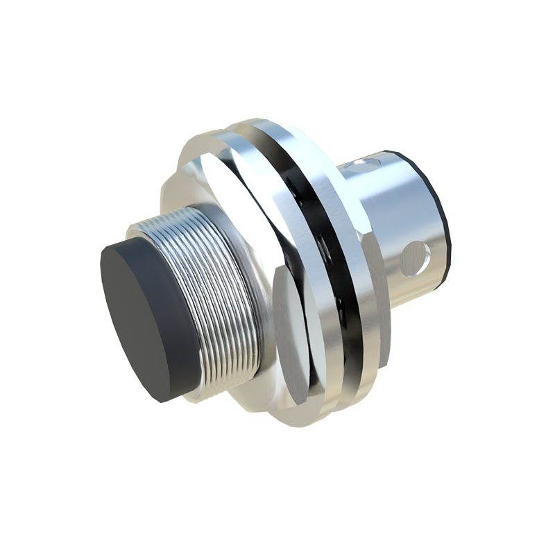
For speed measurement, this principle is applied repetitively. A rotating shaft is often fitted with a toothed wheel or a single protruding target. As each tooth or target passes the sensor's face, it generates a discrete pulse. The speed is then calculated by measuring the frequency of these pulses. The relationship is straightforward: Speed (in RPM) = (Frequency of pulses in Hz 60) / Number of targets per revolution. For instance, a 60-tooth gear generating a 1 kHz pulse frequency corresponds to a shaft speed of 1,000 RPM. This method provides high accuracy and resolution, essential for applications like conveyor belt speed monitoring, motor RPM verification, and overspeed/underspeed protection systems.
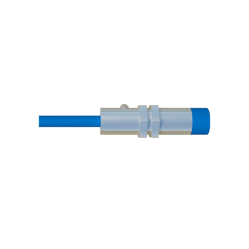
Another prevalent technology is the Hall-effect proximity sensor. These sensors detect changes in a magnetic field rather than inducing eddy currents. A permanent magnet is either embedded in the sensor or mounted on the moving target. As a ferromagnetic target (like a gear tooth) passes, it distorts the magnetic field lines, or a magnetic pole on a rotor passes by the sensor. This change in magnetic flux density is detected by a Hall-effect IC within the sensor, which toggles its output. Hall-effect sensors are highly immune to environmental contaminants like oil, dust, and moisture, making them ideal for harsh conditions. They can also detect both the presence and the polarity of a magnetic field, enabling direction sensing.
Capacitive proximity sensors operate on a different principle, sensing changes in capacitance. The sensor and the target act as two plates of a capacitor. As the target approaches, the capacitance increases until it reaches a threshold that triggers the output switch. While less common for pure speed sensing of metallic objects, they are invaluable for detecting non-metallic materials (plastics, wood, liquids) and can be used in specialized speed monitoring applications involving such materials.
The key advantages of proximity speed sensors are numerous. Their non-contact nature eliminates mechanical wear, ensuring long service life and minimal maintenance. They offer high switching frequencies, often up to several kilohertz, allowing them to measure very high speeds accurately. They are robust, typically housed in stainless steel or nickel-plated brass bodies, with ratings like IP67 or IP69K for resistance to water, dust, and chemicals. The output is usually a clean digital signal (PNP/NPN) or a voltage pulse, easily interfaced with Programmable Logic Controllers (PLCs), frequency counters, or tachometers.
In practical applications, correct installation is critical. The sensing distance, specified as the nominal range (Sn), must be considered. For reliable operation, the target should approach axially to the active face, and the installation should allow for a margin to account for mechanical tolerances and temperature drifts. The target material and size also affect the sensing distance; manufacturers provide reduction factors for different metals. For gear sensing, the tooth size and gap must be compatible with the sensor's switching frequency and physical size.
In conclusion, proximity speed sensors are indispensable for modern industrial control. By leveraging electromagnetic or capacitive fields to generate precise pulse trains corresponding to mechanical movement, they provide a robust, accurate, and maintenance-free solution for monitoring rotational and linear speed. Their integration into safety systems, process control loops, and predictive maintenance frameworks underscores their vital role in enhancing operational efficiency, safety, and reliability across countless industries, from automotive manufacturing to food processing and beyond.