Proximity sensors are indispensable components in modern automation, robotics, and countless industrial applications. Their primary function is to detect the presence or absence of an object within a specified range without physical contact. Understanding how to accurately measure and verify their performance is crucial for ensuring system reliability, safety, and optimal operation. This guide provides a comprehensive, step-by-step approach to measuring key parameters of proximity sensors.
Before beginning any measurement, safety is paramount. Always ensure the system is powered down before making any electrical connections, unless specifically testing live output. Use appropriate personal protective equipment and follow all relevant electrical safety standards. Gather the necessary tools: a stable DC power supply matching the sensor's voltage rating (e.g., 12V or 24V DC), a digital multimeter (DMM), a set of precision gauge blocks or shims for distance measurement, the sensor's datasheet, and the target object specified by the manufacturer.
The first critical measurement is the sensing distance. This is often labeled as Sn, or nominal sensing distance. It is the theoretical operating distance under ideal conditions with a standard target. To measure it, mount the sensor securely. Connect the power supply to the sensor's supply terminals. Connect the multimeter, set to measure DC voltage, across the output signal line and the common (negative) line to monitor the switching state. Using the standard target (typically a square of mild steel, 1mm thick with sides equal to the sensor's diameter or three times the nominal sensing distance), slowly bring it toward the active face of the sensor along the axial centerline. The point at which the output switches (e.g., from 0V to ~24V for a PNP sensor) is the actual operating point. Measure this distance precisely with calipers or gauge blocks. Repeat this process several times while moving the target away to find the release point. The difference between the operate and release points is the hysteresis, a vital parameter for stable switching and preventing chatter.
Next, assess the repeatability of the sensor. This defines its consistency. With the target fixed at approximately 80% of the nominal sensing distance, repeatedly remove and re-insert the target. Use the multimeter to log the voltage switch point each time. The variation in the measured operating distance is the repeatability error, typically a very small value expressed as a percentage of the nominal distance. High repeatability is essential for precision applications.
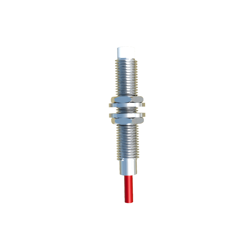
For analog output sensors (e.g., 4-20mA or 0-10V), measurement focuses on the output characteristic curve. You need to map the output signal against the target distance. Secure the sensor and connect the multimeter in series for current measurement or in parallel for voltage measurement. Start with the target beyond the sensing range and record the output (e.g., 4mA or 0V). Gradually move the target closer in small, measured increments, recording the output at each step until the target is at the minimum sensing distance. Plotting this data reveals the sensor's linearity, span, and any potential dead zones. Compare this curve to the one in the datasheet.
Environmental factors significantly impact performance and must be measured or accounted for. Temperature influence can be checked by placing the sensor and target in a controlled thermal chamber, measuring the shift in operating distance across the specified temperature range. For inductive sensors, the material factor is critical. Always use the standard steel target for baseline measurements. Then, test with different materials (aluminum, brass, copper). You will find the sensing distance reduces for non-ferrous metals; this reduction factor is usually provided in the datasheet. Capacitive sensors are affected by the dielectric constant of the target material and environmental humidity, requiring calibration for specific materials.
Finally, verify the electrical performance. Under load, measure the output voltage drop when the sensor is switched on to ensure it can sink or source sufficient current. Use the multimeter to check the leakage current when the sensor is in the "off" state, which should be minimal. Also, measure the response time by rapidly introducing the target and using an oscilloscope to capture the delay between the target's arrival and the output switch.
Regular measurement and calibration of proximity sensors prevent unexpected downtime and maintain product quality. Always refer to the manufacturer's specific documentation, as procedures can vary between inductive, capacitive, ultrasonic, and photoelectric proximity sensor types. By methodically measuring sensing distance, repeatability, output characteristics, and environmental influences, you can fully characterize a sensor's capabilities and integrate it with confidence into any application.