Laser rangefinder sensors have become indispensable tools across numerous industries, from robotics and autonomous vehicles to construction and surveying. Programming these sensors effectively unlocks their full potential, enabling precise distance measurements, object detection, and spatial mapping. This guide delves into the core principles and practical steps for programming laser rangefinder sensors, focusing on common interfaces, data handling, and integration techniques.
Understanding the fundamental operation is crucial before writing any code. A laser rangefinder, typically a time-of-flight (ToF) sensor, emits a laser pulse and measures the time it takes for the reflection to return. This time interval is directly proportional to the distance to the target object. Modern variants, like phase-shift or triangulation-based sensors, offer different trade-offs in range, accuracy, and cost. The programmer's primary task is to communicate with the sensor's hardware to retrieve this raw timing or phase data and convert it into a reliable distance value.
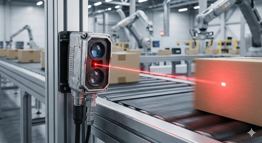
The first step in programming is establishing communication. Most industrial and hobbyist-grade laser rangefinders use serial communication protocols. UART (Universal Asynchronous Receiver/Transmitter) is arguably the most common interface. Here, the sensor acts as a peripheral device sending data packets over TX (transmit) and RX (receive) lines. The programmer must configure the host microcontroller or single-board computer (like an Arduino, Raspberry Pi, or STM32) with the correct baud rate, parity, and stop bits to match the sensor's datasheet specifications. For instance, initializing a UART port at 115200 baud, 8 data bits, no parity, and 1 stop bit is a typical starting point.
I2C (Inter-Integrated Circuit) and SPI (Serial Peripheral Interface) are also prevalent, especially in compact modules where multiple sensors need to share a bus. I2C uses a two-wire interface (SDA and SCL) and is addressable, allowing several sensors on the same bus. SPI offers higher-speed, full-duplex communication using MOSI, MISO, SCLK, and Chip Select lines. The choice of protocol often depends on the required data rate, system complexity, and the host controller's capabilities.
Once communication is stable, the next phase is command and data parsing. Sensors do not continuously stream distance values. They usually require a trigger command. A typical programming sequence involves:

1. Sending a measurement command (e.g., a specific byte sequence like0x01).
2. Waiting for a brief period (the sensor's integration time).
3. Reading the response packet from the sensor's data buffer.
This response packet is rarely a simple integer. It often contains a header, the actual distance data (which may be split across multiple bytes), a checksum for error detection, and a footer. For example, a sensor might return a packet like:[0x59, 0x59, Dist_H, Dist_L, Strength_H, Strength_L, Checksum]. The programmer must extract the high and low bytes of the distance (Dist_H andDist_L), combine them (often using(Dist_H<< 8) | Dist_L), and perform any unit conversion (e.g., from centimeters to meters). Always verify the checksum to ensure data integrity, especially in electrically noisy environments.
Error handling is a critical component of robust sensor programming. Timeouts should be implemented when waiting for a response. Invalid readings, such as values beyond the sensor's minimum or maximum range, or readings with low signal strength (indicating a poor reflection), must be filtered out. Implementing a simple moving average filter or a median filter in your code can significantly smooth noisy data streams and provide more stable readings. For instance, storing the last 10 readings in an array and calculating the median can effectively eliminate occasional outliers.
Advanced programming involves leveraging the sensor's full feature set. Many rangefinders offer programmable parameters like measurement frequency, output data format, or even sensitivity thresholds. Configuring these registers through specific write commands allows customization for the application. In robotics, for fast obstacle avoidance, you might prioritize a high measurement rate (e.g., 100Hz) at the expense of some accuracy. For precision mapping, you would configure the sensor for maximum accuracy, accepting a slower update rate.
Integration into a larger system is the final step. The processed distance data must be formatted and made available to other software components. This could involve publishing the data to a ROS (Robot Operating System) topic, sending it via MQTT for IoT applications, or displaying it on a local dashboard. Using a well-defined data structure or class to encapsulate the distance value, timestamp, and sensor status promotes clean and maintainable code.
In conclusion, programming a laser rangefinder sensor is a multi-stage process involving hardware interfacing,