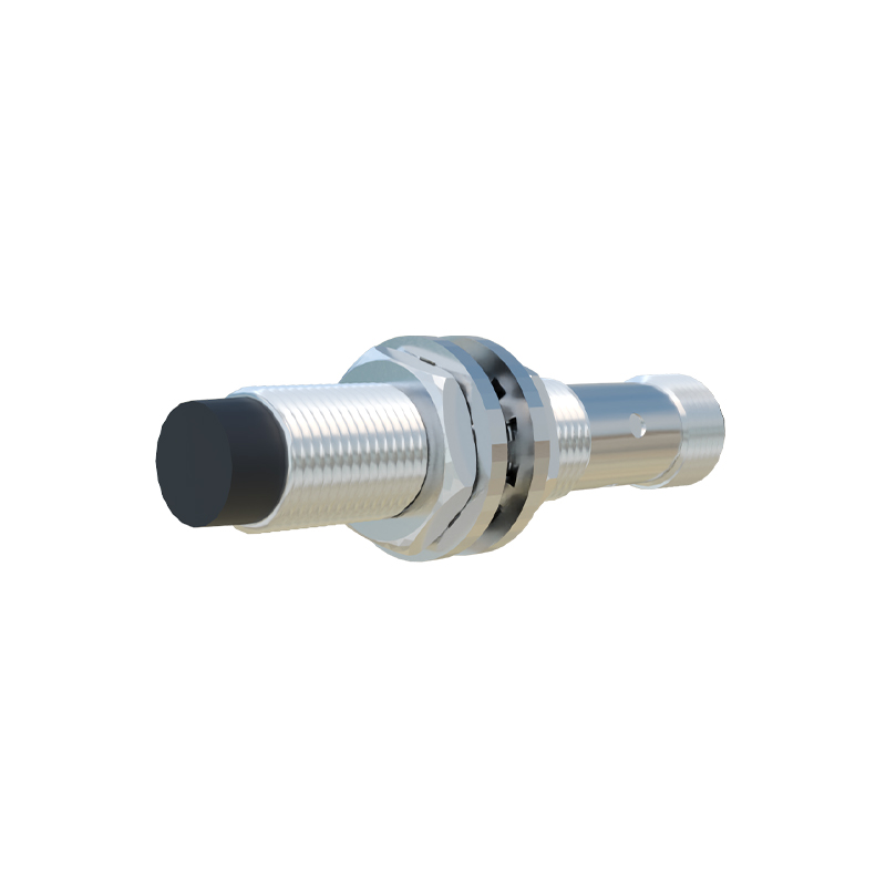
In the realm of industrial automation and machinery monitoring, proximity speed sensors, often referred to as rotational speed sensors or tachometers, play a critical role in ensuring operational safety, efficiency, and process control. Unlike contact-based methods, these non-contact sensors detect the presence, absence, or passage of a target to determine rotational or linear speed. Their principle of operation is elegantly simple yet highly reliable, making them indispensable in harsh environments where mechanical wear, contamination, or high speeds render contact sensors impractical.
The core principle revolves around detecting changes in a physical field—most commonly a magnetic or electromagnetic field—caused by a moving target. The two predominant technologies are inductive proximity sensors and Hall-effect sensors, each with distinct operational mechanics.
Inductive proximity sensors are widely used for metallic targets, typically ferrous metals like iron or steel. The sensor contains an oscillator circuit that generates a high-frequency alternating magnetic field emanating from its active face. When a metallic target, such as a gear tooth, keyway, or a dedicated trigger wheel, approaches this field, eddy currents are induced on the target's surface. These eddy currents draw energy from the oscillator, causing a measurable dampening or attenuation of the oscillation amplitude. An evaluation circuit within the sensor detects this amplitude change and triggers a switching signal—a sharp digital pulse. For speed measurement, a series of evenly spaced targets (like gear teeth) pass by the sensor face. The sensor output is thus a pulse train whose frequency is directly proportional to the rotational speed. The speed (RPM) is calculated by counting the number of pulses per unit time and knowing the number of targets per revolution. These sensors are robust, resistant to dirt, oil, and moisture, and require no physical contact, eliminating wear.
Hall-effect sensors, on the other hand, detect magnetic fields directly. They contain a semiconductor element. When a magnetic field (from a permanent magnet embedded in or attached to the rotating shaft, or from a magnetized target) passes near the sensor, it exerts a force on the moving charge carriers within the semiconductor, generating a small but measurable voltage difference perpendicular to both the current flow and the magnetic field—the Hall voltage. This analog voltage is conditioned and converted into a clean digital pulse. In a typical setup, a multi-pole magnetic ring or a simple magnet passes by the Hall sensor, generating one pulse per pole pair. Hall sensors can detect both ferrous and non-ferrous metals, as long as a magnetic field is present. They offer excellent accuracy at very low speeds, even down to zero RPM, and are highly immune to environmental contaminants.
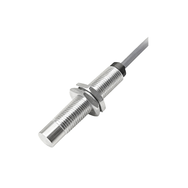
The output signal from these sensors is crucial. It is typically a square wave pulse (NPN or PNP transistor output). This digital signal is fed into a programmable logic controller (PLC), frequency counter, tachometer, or data acquisition system. The system measures the time interval between consecutive pulses or counts pulses over a fixed time window to compute the instantaneous speed. Advanced diagnostics can also be performed by monitoring the pulse consistency to detect missing teeth, shaft wobble, or impending bearing failure.
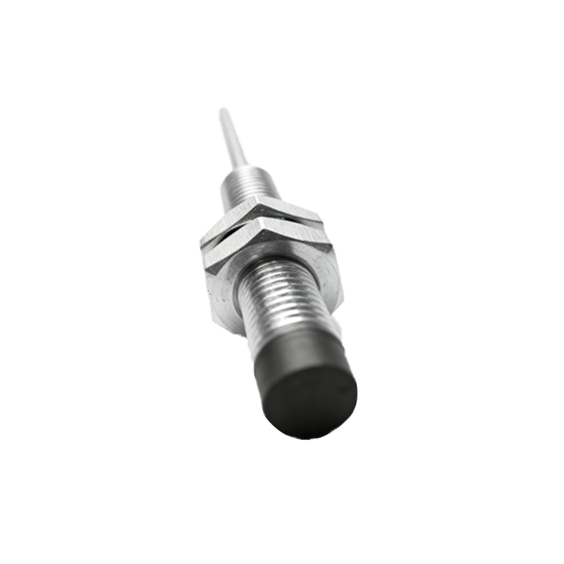
Key application areas highlight their importance. They are fundamental in motor speed control and feedback within variable frequency drives (VFDs), ensuring precise RPM regulation. On conveyor systems, they monitor belt speed for synchronization and slip detection. In automotive and aerospace, they measure crankshaft and camshaft position/speed for engine management and anti-lock braking systems (ABS). They protect machinery by providing overspeed and underspeed trip signals for turbines, fans, and pumps. Furthermore, they are used in counting applications, such as monitoring production rates on packaging lines.
Selecting the right proximity speed sensor involves several considerations. The target material dictates the technology: inductive for ferrous metals, Hall-effect for magnetic fields. The required sensing distance, operating temperature range, environmental protection rating (IP rating), supply voltage, output type, and the required resolution (determined by the number of pulses per revolution) are all critical parameters. Proper installation is equally vital; the sensor must be mounted at the correct gap (air gap) from the target, aligned properly to avoid skewed readings, and shielded from excessive vibration and electromagnetic interference from nearby motors or power lines.
In summary, proximity speed sensors provide a robust, non-intrusive method for rotational and linear speed measurement by exploiting fundamental electromagnetic principles. Their ability to deliver reliable digital feedback in demanding conditions forms the backbone of modern industrial monitoring and control systems, directly contributing to predictive maintenance, energy efficiency, and overall operational safety. Understanding their operating principles allows engineers to specify, install, and maintain these sensors effectively, ensuring optimal performance across countless industrial applications.