In the realm of industrial automation and machinery control, the integration of proximity sensors with electric motors represents a critical enhancement for precision, safety, and operational intelligence. As a seasoned electrical engineer, I will delineate a comprehensive, step-by-step methodology for this installation, adhering to industry best practices and safety protocols. The primary objective is to enable non-contact detection of motor shaft position, rotational speed, or the presence of specific components, thereby facilitating advanced control sequences, predictive maintenance, and fault prevention.
The initial phase involves meticulous planning and selection. Not all proximity sensors are created equal. For motor applications, inductive proximity sensors are predominantly used for detecting metallic targets, such as gear teeth or keyways on a motor shaft. Key selection parameters include:
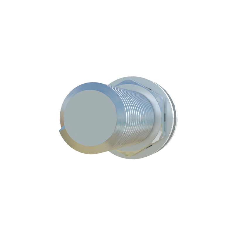
1. Sensor Type: Inductive (for metals), capacitive (for non-metals, less common in pure motor sensing), or magnetic (Hall-effect for detecting magnetic fields from magnets mounted on the shaft).
2. Sensing Distance: The nominal range must be suitable for the expected air gap between the sensor face and the target. A 2mm to 8mm range is typical, but refer to the sensor's datasheet for precise specifications.
3. Output Type: PNP (sourcing) or NPN (sinking) transistor outputs are standard, compatible with PLCs (Programmable Logic Controllers) and motor drives. The choice must align with the control system's input card specifications.
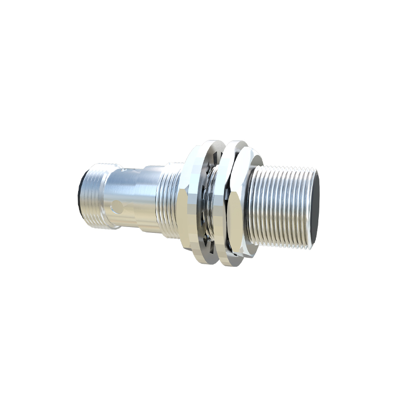
4. Electrical Characteristics: Operating voltage (commonly 10-30V DC), current rating, and connection type (pre-wired cable or quick-disconnect).
5. Environmental Rating: The housing must be robust enough for the operating environment—typically IP67 or higher for resistance to dust, oil, and coolant ingress.
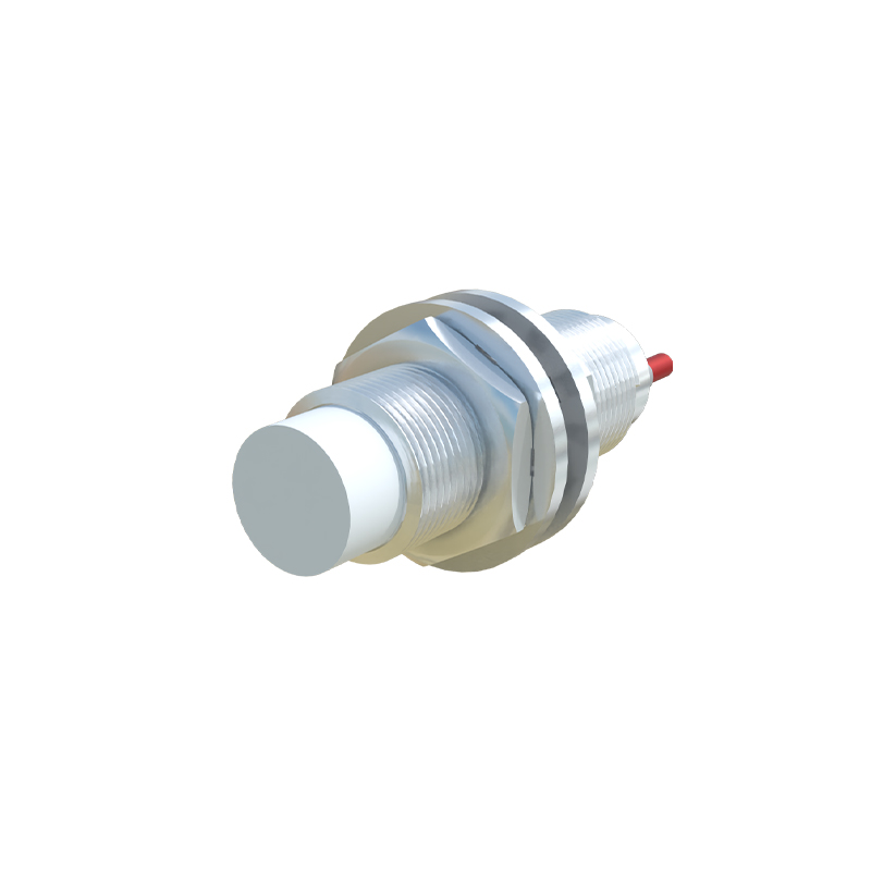
6. Physical Form Factor: Cylindrical (e.g., M8, M12, M18, M30 threaded barrels) or rectangular block styles, chosen based on mounting space constraints.
Once the appropriate sensor is procured, the installation process commences with absolute safety as the paramount concern. Ensure the motor is completely de-energized, locked out, and tagged out (LOTO). Verify zero voltage at the motor terminals using a multimeter.
Step 1: Mounting Bracket Design and Fabrication.
Rarely will a motor have a ready-made mount for a proximity sensor. A custom bracket is usually required. This bracket must be rigid, typically fabricated from steel or aluminum, to prevent vibration-induced misalignment. It should securely attach to the motor's end-bell, baseplate, or a nearby fixed structure. The design must allow for precise radial and axial adjustment of the sensor relative to the target on the motor shaft.
Step 2: Target Preparation.
The target is the feature on the rotating component that the sensor will detect. Common configurations include:
Single-Point Detection: A single bolt head, a keyway, or a small piece of ferrous metal attached to a coupling. This provides one pulse per revolution for speed measurement.
Multi-Point Detection: A gear or a slotted disk. This provides multiple pulses per revolution for higher-resolution position or speed feedback.
The target must be clean, free of debris, and made of the appropriate material (ferrous for inductive sensors). Ensure it is securely fastened to prevent detachment at high rotational speeds.
Step 3: Sensor Mounting and Alignment.
Mount the sensor into its bracket using the appropriate locknuts. The critical adjustment is the air gap—the distance between the active face of the sensor and the target. This must be set within the sensor's specified operating range, typically 50% to 80% of its nominal sensing distance. Use a non-magnetic feeler gauge for precise setting. Misalignment can cause inconsistent sensing or complete failure. The sensor face should be parallel to the target surface for axial sensing, or properly oriented for radial sensing of gear teeth.
Step 4: Electrical Wiring.
Follow the sensor manufacturer's wiring diagram meticulously. A standard 3-wire DC sensor has Brown (Live/+V), Blue (Common/0V), and Black (Output) wires. Some have additional White (Output 2) wires.
Connect the Brown wire to the positive DC supply (e.g., +24V).
Connect the Blue wire to the DC common/negative.
Connect the Black (output) wire to the input channel of your PLC, drive, or counter.
Always use shielded cable for the sensor leads, grounding the shield at the control panel end only to mitigate electromagnetic interference (EMI) from the motor's magnetic fields and drive's switching frequencies.
Step 5: Testing and Commissioning.
Before re