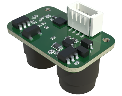
In modern industrial automation and precision measurement applications, laser sensors have become indispensable tools for non-contact detection, distance measurement, and positioning. However, integrating these sensitive electronic devices into environments with Electrostatic Discharge (ESD) risks requires careful planning and execution. This article provides a comprehensive guide for electrical engineers on properly connecting laser sensors to ESD-protected systems, ensuring both operational reliability and longevity of the equipment.
Understanding the core challenge is paramount. Laser sensors, particularly those with CMOS or CCD imaging elements and sensitive signal processing circuits, are highly vulnerable to ESD events. A sudden electrostatic discharge, often imperceptible to humans, can cause latent damage, degradation, or immediate catastrophic failure of the sensor's internal electronics. This vulnerability extends beyond the sensor itself to the entire data acquisition chain. Therefore, the connection strategy must focus on creating a continuous, low-resistance path to ground for any static charges, while simultaneously protecting the sensor's signal integrity.
The foundation of a robust connection lies in establishing a Common Ground Point (CGP). All equipment, including the laser sensor, its power supply, the programmable logic controller (PLC), and the host machine or conveyor system, must be bonded to a single, dedicated ground point. This star-point grounding topology prevents ground loops, which can introduce noise into sensitive analog or digital signals from the sensor. Use heavy-gauge copper braiding or straps for bonding machine frames to the CGP, ensuring impedance is less than 1 ohm as per ANSI/ESD S6.1 standards.

For the physical electrical connection, the choice of cable and wiring practice is critical. Shielded cables are non-negotiable. Select cables with a high-coverage-rate braided shield, preferably with an aluminum foil layer for full-frequency shielding. The cable shield must be terminated 360 degrees circumferentially at both ends using proper glanded cable entries or shielded connector backshells. At the sensor end, connect the shield directly to the sensor's metallic housing if it is designated as the ground terminal. At the control panel end, bond the shield to the panel's ground busbar, which is directly connected to the CGP. Importantly, the shield should carry only ESD and noise currents, not the signal return current.
Power supply isolation is another key consideration. Use an isolated DC/DC power supply or a dedicated linear regulated power supply for the laser sensor. This prevents noise and transients from the main power bus from coupling into the sensor. Incorporate transient voltage suppression (TVS) diodes or multilayer varistors (MLVs) at the power input terminals of the sensor. These components clamp any voltage spikes from ESD or inductive load switching, diverting harmful energy to ground before it reaches the internal circuitry.
Signal line protection is equally vital. For digital output sensors (PNP/NPN), install ESD protection devices, such as steering diodes or specialized ICs like Bourns' CDSOT23-SM712, on the output lines close to the sensor's connector. For analog output sensors (0-10V, 4-20mA), consider using signal conditioners or isolators with built-in ESD protection. These devices provide galvanic isolation, breaking ground loops and offering a high common-mode rejection ratio (CMRR) to suppress noise. Ensure all I/O lines entering or leaving the control panel pass through a bonded metal plate that connects their shield drains to the panel ground.
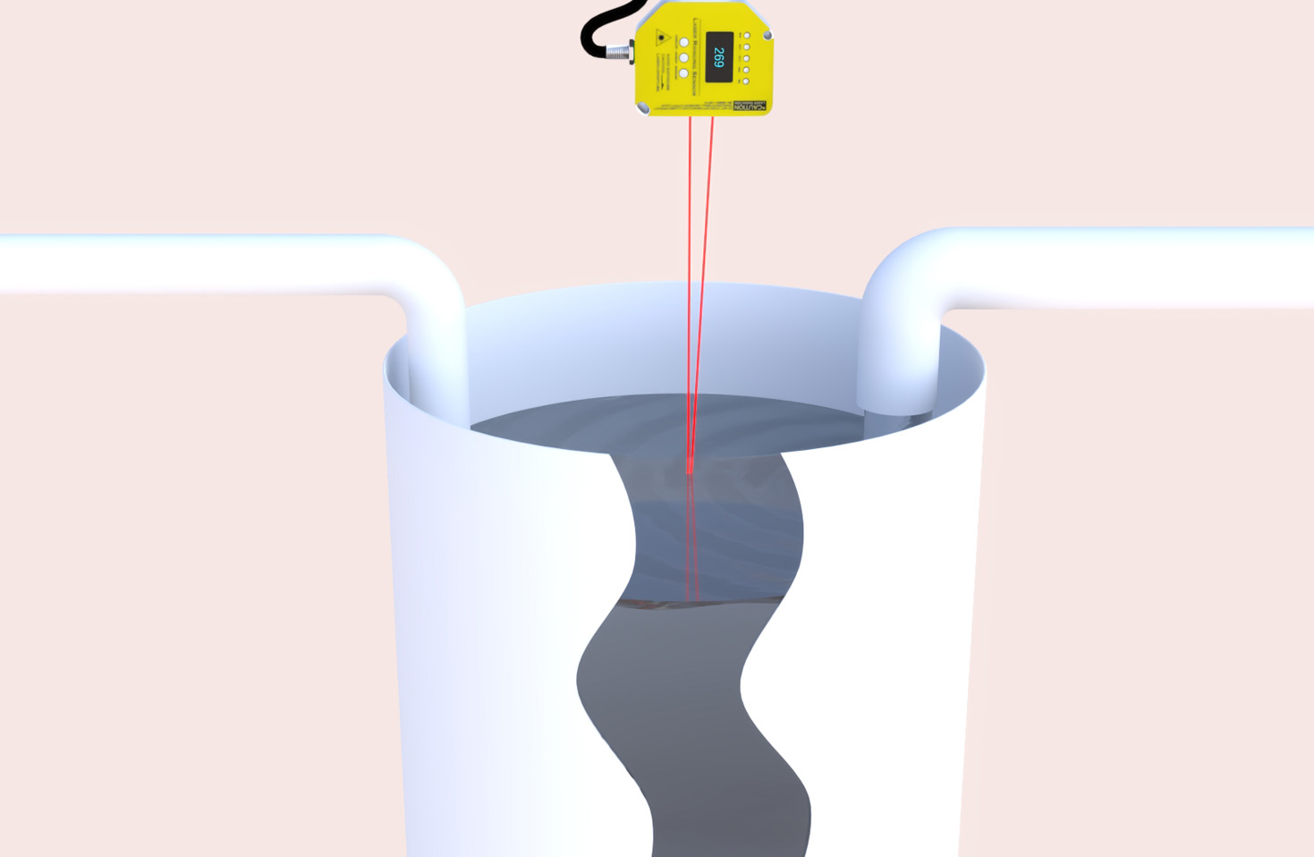
Finally, implement comprehensive environmental controls. Maintain relative humidity in the operating area between 40% and 60% to minimize static charge generation. Use conductive or dissipative mats on workstations where sensors are handled. All personnel should wear properly grounded wrist straps when installing or servicing the sensor. The sensor's mounting bracket should be made of conductive material and bonded to the machine ground. Regularly verify the integrity of all ground connections using a certified ground bond tester.
By methodically applying these principles—establishing a single-point ground, using and properly terminating shielded cables, isolating power supplies, protecting signal lines, and controlling the environment—engineers can create a reliable interface between laser sensors and ESD-prone systems. This proactive approach mitigates downtime, reduces maintenance costs, and ensures the high-precision data from laser sensors drives process efficiency and quality control without interruption.