Calibration is a critical process in ensuring the accuracy, reliability, and repeatability of laser sensor measurements. Whether used for distance measurement, object detection, alignment, or profiling in industrial automation, quality control, or robotics, a properly calibrated laser sensor is fundamental to system performance. This guide outlines a systematic, engineering-focused approach to laser sensor calibration.
The calibration process essentially aligns the sensor's output with a known physical standard, correcting for systematic errors. Before beginning, gather the necessary equipment: a certified calibration target or gauge (e.g., precision gauge blocks, a flat white surface of known reflectivity, or a dedicated calibration fixture), a stable mounting platform, the sensor's datasheet and software interface, and appropriate environmental controls to minimize variables like ambient light, vibration, and temperature fluctuations.
Step 1: Pre-Calibration Preparation
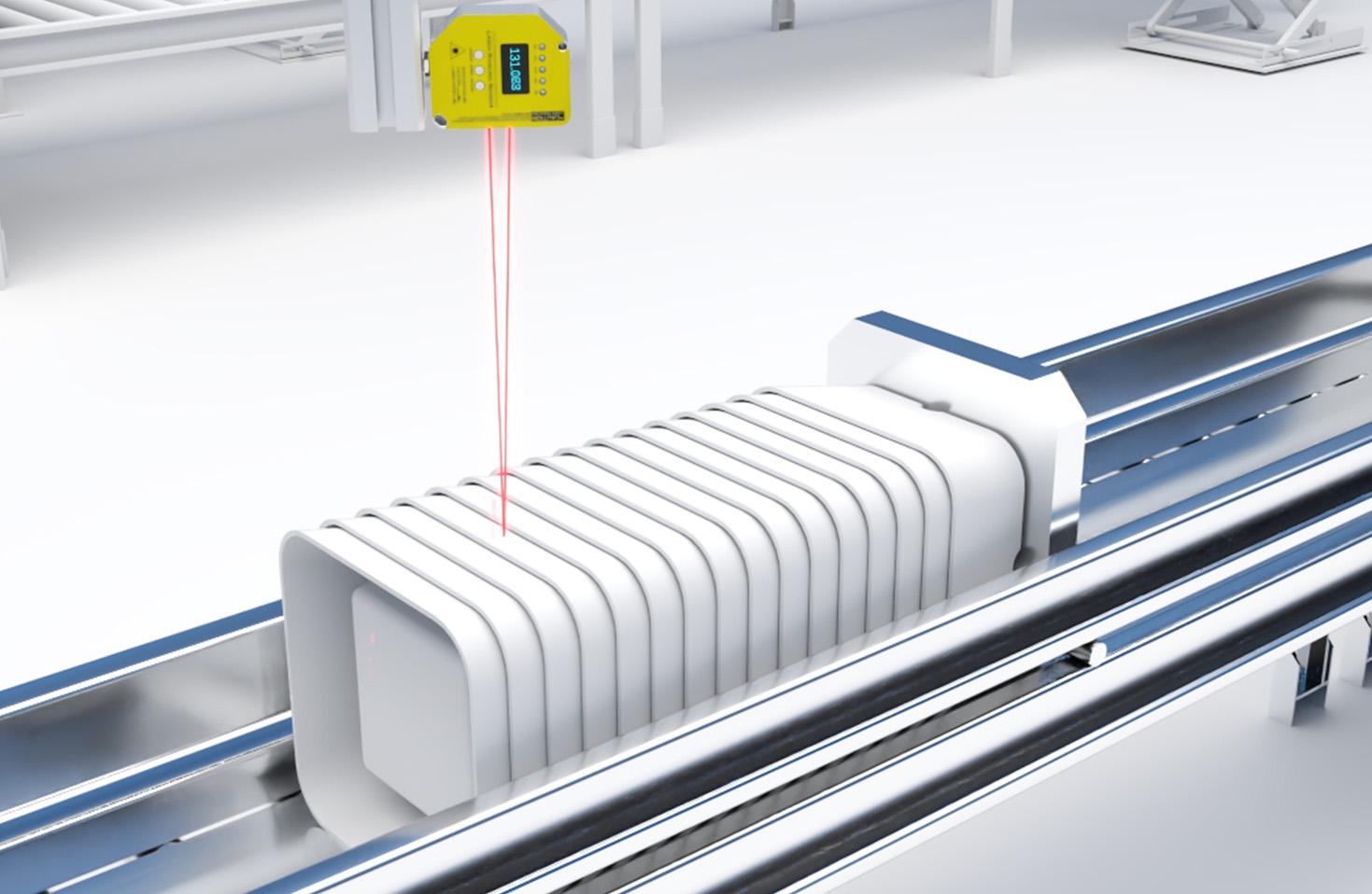
Power on the sensor and allow it to warm up for the time specified in the manufacturer's manual—typically 15-30 minutes—to stabilize its internal electronics and laser diode. Ensure the sensor is securely mounted in its operational orientation. The calibration target should be placed perpendicular to the laser beam's axis. Verify the operating environment is within the sensor's specified temperature and humidity ranges, as these factors can affect wavelength and measurement stability.
Step 2: Establish Communication and Baseline
Connect the sensor to its configuration software via the appropriate interface (e.g., Ethernet, USB, RS-232). Access the calibration or teaching menu. First, record the sensor's current raw output readings against the calibration target at a known, fixed distance. This establishes a baseline, highlighting any initial offset or gain error. Consult the datasheet for the sensor's defined measurement range and standard response curve.
Step 3: Multi-Point Calibration
For most analog and digital output sensors, a multi-point calibration is recommended for linearization.
- Point 1 (Near Point): Position the calibration target at the minimum measurement distance (S_min). Command the sensor to "learn" or set this point. The output (e.g., 0V, 4mA, or a specific digital value) should now correspond to this known distance.
- Point 2 (Far Point): Move the target to the maximum measurement distance (S_max). Repeat the learning process so the maximum output (e.g., 10V, 20mA) corresponds to this distance.
- Optional Intermediate Points: For high-precision applications, teach additional points at 25%, 50%, and 75% of the measurement range. This corrects non-linearity in the sensor's characteristic curve.
For sensors with switching outputs, calibration involves setting the precise trigger threshold. Position the target at the exact switch point distance and adjust the threshold until the output reliably changes state.
Step 4: Parameter Adjustment and Linearization
The sensor software will often generate a linearization table or apply a correction algorithm based on the taught points. Key parameters to verify or adjust include:
- Offset (Zero Point): Corrects the systematic shift where the output is non-zero at the minimum reference distance.
- Gain (Span): Adjusts the slope of the input-output relationship so the span between min and max outputs matches the physical span.
- Filter Settings: Adjust response time or averaging filters to reduce noise without introducing unacceptable lag.
Step 5: Validation and Documentation
After applying calibration parameters, perform a validation sweep. Move the target through the entire measurement range, taking readings at several intervals not used during the teaching process. Compare the sensor's reported values against the known positions of the target (measured with a traceable standard like a laser interferometer or high-precision encoder). Calculate the error: Error = Measured Value - True Value. Ensure the maximum error is within the sensor's specified accuracy tolerance. Document all calibration data: date, environmental conditions, reference standards used, pre- and post-calibration error values, and the technician's name. This creates an audit trail for quality systems like ISO 9001.
Step 6: Post-Calibration Considerations
Re-calibration frequency depends on the application's criticality, operational environment, and sensor stability. Harsh environments with thermal cycling, mechanical shock, or contamination necessitate more frequent checks. Implement a scheduled maintenance plan. Monitor for drift by periodically checking against a fixed reference. Remember, calibration compensates for sensor drift but cannot repair physical damage to the lens or laser emitter.
In summary, meticulous laser sensor calibration is not merely a one-time setup but a core component of sustainable measurement integrity. By following a disciplined procedure using traceable standards and thoroughly documenting the process, engineers ensure that these sophisticated optical devices deliver the precise, trustworthy data upon which modern automated systems depend.