In the realm of industrial automation and control systems, proximity sensors are indispensable components. A fundamental parameter that engineers and technicians must carefully consider during selection and integration is the working current. This specification is crucial for ensuring reliable operation, system compatibility, and optimal performance. This article delves into the typical working current ranges for various types of proximity sensors, the factors influencing these values, and key considerations for practical application.
Proximity sensors operate by detecting the presence or absence of a target object without physical contact. Common types include inductive, capacitive, and photoelectric sensors. Each type has distinct operating principles and, consequently, different electrical characteristics, including their current consumption.
Typical Working Current Ranges
The working current, often specified as the load current or operating current, refers to the current drawn by the sensor itself during normal operation, excluding any output switching current. For most standard industrial DC-powered proximity sensors, the working current typically falls within a range of 5 mA to 25 mA. This is the current consumed by the sensor's internal oscillator, amplifier, and processing circuitry.
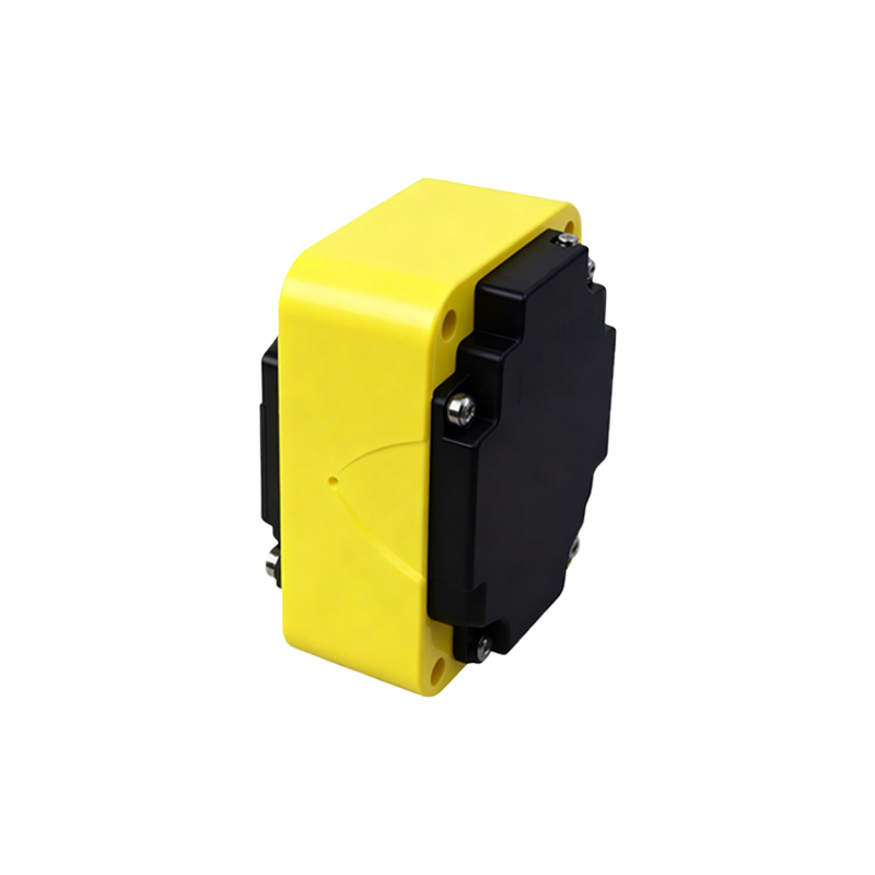
However, this is a general range. Specific values depend heavily on the sensor type, size, sensing distance, and features. For instance:
Inductive Sensors: Commonly used for metal detection, compact tubular models (e.g., M8, M12) often have a working current between 5-15 mA. Larger barrel sensors (e.g., M18, M30) or those with extended sensing ranges may draw up to 20-25 mA due to larger coil windings.
Capacitive Sensors: Used for detecting non-metallic materials, their working current is similar to inductive types, generally in the 8-20 mA range.
Photoelectric Sensors: These can vary more widely. Basic diffuse-reflective models might draw 10-20 mA. More sophisticated models with background suppression, fiber optic amplifiers, or long-range through-beam sensors can have working currents from 15 mA up to 40-50 mA, especially if they incorporate powerful LEDs or laser diodes and complex signal processing.
Output Stage and Load Current: A Critical Distinction
It is paramount to distinguish between the sensor's working current and its output switching current (or load current). The working current is constant and drawn from the power supply. The output current is the maximum current the sensor's output switch (typically a solid-state transistor or a relay) can handle to drive an external load like a PLC input, relay coil, or indicator lamp.
For a standard 3-wire DC sensor (PNP or NPN), the datasheet will list:
1. Supply Current / No-load Current: This is the working current (e.g., ≤15 mA).
2. Max. Load Current: This is the capacity of the output switch (e.g., 200 mA).
The total current drawn from the power supply will be the sum of the sensor's working current and the current flowing through the load connected to its output. Power supply sizing must account for both.
Factors Influencing Working Current
Several factors affect the actual working current:
Supply Voltage: While designed for a nominal voltage (e.g., 10-30 VDC), current consumption may slightly increase with higher voltage.
Output State: Some sensors may draw marginally different current when the output is active (ON) versus inactive (OFF).
Sensing Frequency: High-speed sensors or those in constant detection cycles might exhibit an average current close to the maximum specified.
Additional Features: Sensors with built-in diagnostics (IO-Link), analog outputs, or short-circuit protection circuits may have a higher base working current.
Environmental Conditions: Extreme temperatures can affect semiconductor behavior, potentially altering current draw.
Application Considerations and Best Practices
1. Power Supply Sizing: Always calculate the total current requirement for all sensors and their loads on a circuit. Ensure the power supply has sufficient capacity with a safety margin (typically 20-30% headroom).
2. Wiring and Voltage Drop: Using undersized cables for long wire runs can cause significant voltage drop due to the working current. This can lead to sensors malfunctioning due to undervoltage. Adhere to recommended wire gauges.
3. Heat Dissipation: In densely packed control cabinets with hundreds of sensors, the cumulative working current contributes to heat generation. Proper ventilation is necessary.
4. Energy Efficiency: For large-scale installations or battery-operated systems, selecting sensors with a lower working current can lead to meaningful energy savings and longer battery life.
5. Consult the Datasheet: Never assume current ratings. The manufacturer's datasheet is the definitive source for the specific model's electrical characteristics, including typical and maximum working current.