In the rapidly evolving landscape of industrial automation and smart device design, mini proximity sensors have become indispensable components. Their compact size, high reliability, and non-contact detection capabilities make them ideal for a vast array of applications, from precision assembly lines to consumer electronics. This guide provides a comprehensive, practical overview of how to effectively integrate and utilize these powerful sensing devices.
Understanding the Core Technology
Mini proximity sensors operate on the principle of detecting the presence or absence of a target object without physical contact. The most common types are inductive, capacitive, and photoelectric sensors in miniature form factors. Inductive sensors detect metallic objects using an electromagnetic field. Capacitive sensors can detect both metallic and non-metallic materials (like liquids, plastics, or wood) by sensing changes in capacitance. Mini photoelectric sensors use a light beam, typically infrared, to detect objects. The choice depends entirely on the application's material, sensing distance, and environmental conditions.
Key Steps for Proper Implementation
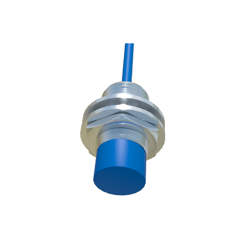
1. Selection and Specification: The first step is choosing the right sensor. Critical parameters include:
Sensing Distance: The nominal operating distance (Sn). For mini sensors, this typically ranges from 1mm to 15mm. Always account for a reduction factor for different metals (for inductive types) and ensure a 10-20% safety margin.
Output Type: Digital outputs (PNP/NPN) are standard. PNP (sourcing) outputs switch the positive voltage to the load, while NPN (sinking) switches the negative side. Ensure compatibility with your PLC or controller input card.
Size and Form Factor: Cylindrical (e.g., M5, M8, M12 threads) and rectangular block styles are common. Consider the physical space constraints in your design.
Environmental Rating: Look for IP67 or higher ratings for protection against dust and temporary immersion, crucial for washdown or harsh environments.
2. Correct Installation and Mounting: Proper mounting is non-negotiable for reliable operation. For inductive sensors, maintain the specified lateral and axial clearance from metal mounting surfaces and other sensors to prevent mutual interference. Use non-ferromagnetic mounting hardware (e.g., stainless steel). Ensure the target approaches the sensor's sensing face correctly. For cylindrical sensors, flush-mounted models can be installed level with a metal bracket, while non-flush types require a clear frontal area but offer longer sensing ranges.
3. Wiring and Electrical Connection: Adhere strictly to the manufacturer's datasheet. A typical 3-wire DC sensor has connections for Brown (+V), Blue (0V/Common), and Black (Output). Always implement protective measures such as fuses or circuit breakers. For long cable runs in electrically noisy environments, use shielded cables and ground the shield at the controller end only. Pay close attention to polarity to prevent damage.
4. Alignment and Testing: After installation, power the system and methodically test the sensor with the intended target. Use the sensor's built-in indicator LED (a standard feature) to confirm detection. Fine-tune the sensor's position to achieve a consistent and reliable switching signal. For adjustable models, use a non-metallic tool to calibrate the sensitivity potentiometer if necessary, avoiding over-sensitivity that could cause false triggers.
5. Integration with Control Systems: The sensor's output is fed into a PLC, microcontroller, or relay. Implement debounce logic in software or hardware to filter out mechanical vibration or electrical noise. For high-speed counting or positioning applications, verify the sensor's response frequency (switching speed) is adequate for the target's velocity.
Common Application Examples
Position Verification: Confirming a part is present in a fixture or a robotic gripper has closed.
End-of-Travel Detection: Sensing the limit of a linear actuator or cylinder in compact machinery.
Counting and Sorting: Detecting small components on a high-speed conveyor.
Thread Detection: Verifying the presence of a metal screw or nut before a process step.
Level Sensing: Using a capacitive mini sensor to detect fluid or powder levels in small containers.
Troubleshooting Best Practices
Most issues stem from incorrect installation or selection. If a sensor fails to trigger, check: power supply voltage, wiring connections, target material and size (is it within the minimum detectable object specification?), and accumulated debris on the sensing face. Environmental factors like extreme temperatures, strong magnetic fields, or chemical splashes can also affect performance. Always consult the sensor's operating manual for specific diagnostic procedures.
By following these engineering-focused guidelines, you can leverage mini proximity sensors to enhance system reliability, enable miniaturization, and add intelligent feedback to your designs. Their correct application is a blend of technical