In industrial automation, proximity sensors play a critical role in detecting the presence or absence of objects without physical contact. Proper wiring is essential to ensure reliable operation and longevity. This tutorial video guide provides a step-by-step approach to wiring proximity sensors, covering key aspects from selection to commissioning.
First, identify the sensor type: inductive, capacitive, or ultrasonic. Inductive sensors detect metallic objects, capacitive sensors handle non-metallic materials, and ultrasonic sensors are suitable for various substances based on distance. Check the sensor specifications, including operating voltage (typically 10-30V DC or 90-250V AC), output type (PNP or NPN for DC, NO or NC for AC), and housing style (barrel, rectangular, or ring).
For DC sensors, begin by disconnecting power to the control system. Locate the sensor's wiring diagram, usually printed on the body or in the datasheet. A three-wire DC sensor includes brown (positive), blue (negative), and black (output) wires. Connect the brown wire to the positive terminal of the power supply and the blue wire to the negative terminal. The black wire links to the PLC input or relay. For PNP sensors, the output provides positive voltage when activated; for NPN, it switches the negative side. Ensure the load (e.g., PLC input) is compatible with the sensor's output configuration.
Two-wire AC sensors simplify wiring but require careful current matching. Connect one wire to the live AC terminal and the other to the load, which then returns to the neutral. Verify the sensor's minimum and maximum current ratings to avoid malfunction. Shielded cables are recommended for long runs or electrically noisy environments to prevent interference. Ground the shield at one end only, typically at the control panel.
In the video, practical demonstrations show how to test the sensor using a multimeter. Set the multimeter to voltage mode for DC sensors or continuity mode for AC types. Actuate the sensor by bringing a target within its sensing range. A PNP sensor should show voltage close to the supply level between the black and blue wires when triggered. For NPN, measure between brown and black wires. Incorrect readings may indicate reversed polarity or faulty connections.
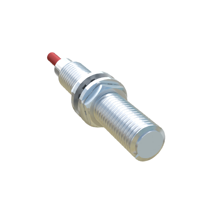
Mounting considerations are also covered. Ensure the sensor is securely fixed, with proper alignment to the target. Maintain the specified sensing distance, and avoid metal-to-metal contact for inductive sensors to prevent false triggers. Environmental factors like temperature, humidity, and chemical exposure should match the sensor's IP rating.
Finally, commission the system by applying power and observing the indicator LED. Most sensors have an LED that lights when activated. Integrate the sensor into the control logic, programming the PLC or relay for the desired response. Troubleshoot common issues: no output may stem from incorrect wiring or insufficient target material, while erratic behavior often results from electrical noise or grounding problems.
This video guide emphasizes safety—always follow lockout-tagout procedures and use personal protective equipment. Regular maintenance, such as cleaning the sensing face and checking connections, enhances performance. By mastering these wiring techniques, engineers can optimize sensor reliability in applications from conveyor systems to robotic cells.
For advanced users, the tutorial explores daisy-chaining multiple sensors and interfacing with industrial networks like IO-Link. These methods reduce wiring complexity and enable real-time diagnostics. Remember, consulting manufacturer guidelines ensures compliance with specific model requirements, as variations exist across brands. With clear visuals and detailed explanations, this video serves as a comprehensive resource for both beginners and experienced technicians in the electrical engineering field.