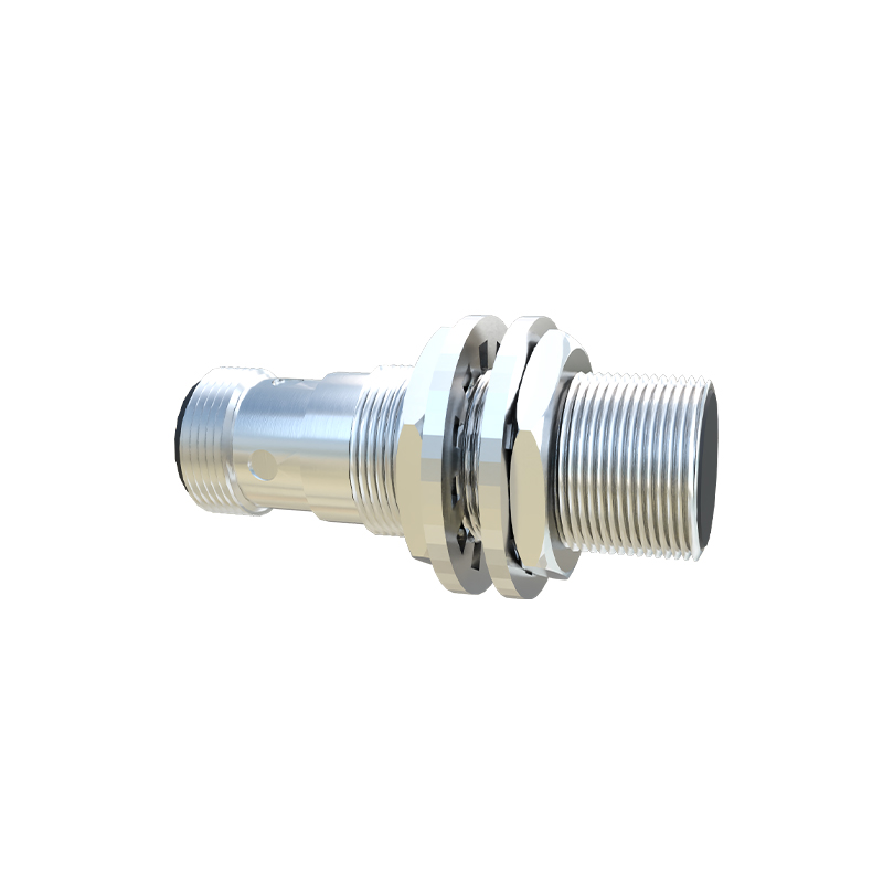
In the world of electronics and automation, proximity sensors are fundamental components. They detect the presence or absence of an object without physical contact, enabling countless applications from security systems to touchless switches. While commercial sensors are readily available, building your own simple proximity sensor is an excellent educational project that deepens your understanding of basic electronic principles, such as capacitance, inductance, or infrared reflection. This guide will walk you through creating a basic capacitive proximity sensor, one of the most straightforward types to DIY using common components.
The core principle behind our capacitive sensor is the change in capacitance. Every conductor possesses capacitance. When your hand or a metallic object approaches a conductive sensor plate, it alters the local electrostatic field, effectively increasing the capacitance. Our circuit will detect this minute change and convert it into a clear output signal, like lighting an LED. For this project, you will need a 555 timer IC (configured in astable mode), a resistor (e.g., 10kΩ), two capacitors (e.g., 10nF and 100nF), an LED, a current-limiting resistor for the LED (e.g., 330Ω), a 9V battery with a connector, a breadboard, jumper wires, and a small metal plate or piece of aluminum foil to act as the sensing element.
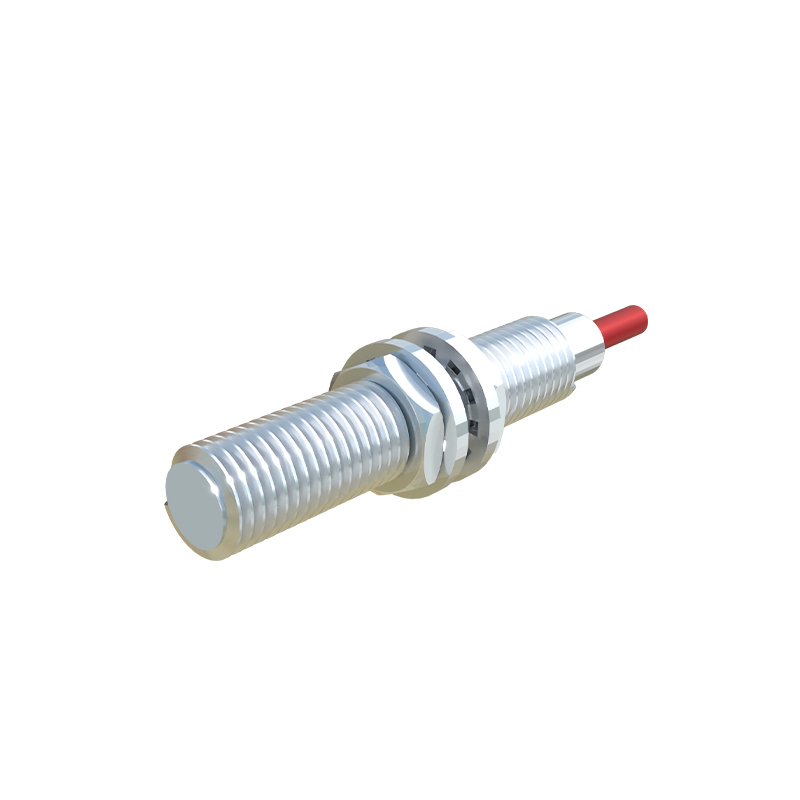
Begin by placing the 555 timer IC on the breadboard, straddling the center gap. Connect pin 1 (Ground) to the negative rail of the breadboard. Connect pin 8 (Vcc) to the positive rail. Now, for the core timing circuit: connect a 10kΩ resistor between pin 7 (Discharge) and the positive rail. Next, connect one lead of the 10nF capacitor to pin 6 (Threshold) and also to pin 2 (Trigger). Connect the other lead of this capacitor to the negative rail. This 10nF capacitor is the key component whose effective value will be influenced by proximity. To create our sensing plate, attach a wire from the junction of pin 2, pin 6, and the 10nF capacitor. Connect the other end of this wire to your metal plate or foil. This plate is now part of the timing circuit. Connect a 100nF capacitor between pin 5 (Control Voltage) and the negative rail for stability. Finally, for the output, connect pin 3 (Output) through a 330Ω current-limiting resistor to the anode of the LED. Connect the cathode of the LED to the negative rail.
The theory of operation is elegant in its simplicity. The 555 timer is wired as an astable multivibrator, generating a continuous square wave. The frequency of this wave is determined by the resistor and the capacitor connected to pins 2 and 6—our 10nF capacitor plus the variable capacitance of the sensor plate. When no object is near the sensor plate, the circuit oscillates at a baseline frequency. As your hand approaches the plate, the capacitance increases. This increased capacitance slows down the charging/discharging cycle of the timing circuit, thereby lowering the output frequency at pin 3. We are not directly measuring this frequency change; instead, we are using a neat trick. Connect a multimeter set to measure frequency between pin 3 and ground. You will observe the frequency drop as you bring your hand closer. For a more visual indication, the LED's brightness might appear to change subtly due to the shifting duty cycle, but for a clearer on/off effect, you can add a simple transistor switch or a 555 configured as a monostable triggered by the frequency shift.
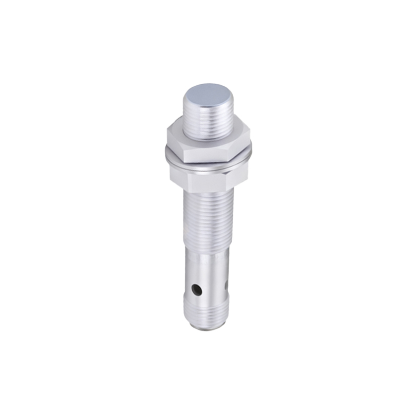
Power the circuit using the 9V battery connected to the breadboard's power rails. With no object nearby, note the LED's state or the frequency reading. Slowly move your hand toward the sensor plate. You should observe the LED behavior change or the measured frequency decrease. The sensitivity depends on the size of the sensor plate and the initial value of the fixed capacitor. Experiment by increasing the size of the metal plate or decreasing the value of the 10nF capacitor to increase sensitivity. Remember, this is a very basic sensor. It can be affected by humidity, temperature, and electrical noise. For more stable and reliable detection, consider shielding the sensor wire with a grounded sheath and adding a potentiometer in series with the 10kΩ resistor to fine-tune the baseline frequency.
This DIY capacitive proximity sensor, while simple, opens the door to practical modifications. You can replace the LED with a relay module to control AC appliances, creating a touchless lamp switch. Integrating the output with an Arduino or Raspberry Pi allows for distance estimation and data logging. The project solidifies concepts of RC time constants, oscillator circuits, and capacitive sensing. Always remember to work safely with low-voltage DC circuits. With