In industrial automation and control systems, proximity sensors are indispensable components, providing non-contact detection of metallic or, in some cases, non-metallic objects. Their reliability is paramount for ensuring smooth production flow, machine safety, and process accuracy. However, like any electronic device, proximity switches can fail or exhibit erratic behavior, leading to costly downtime and potential safety hazards. This article delves into the common reasons why a proximity sensor might stop working and provides a systematic approach to troubleshooting and resolution.
A proximity sensor not working typically manifests in several ways: no output signal when a target is present, a constant output signal regardless of target position, intermittent operation, or a reduced sensing range. The root causes can be broadly categorized into electrical issues, mechanical/environmental factors, and sensor selection or configuration errors.
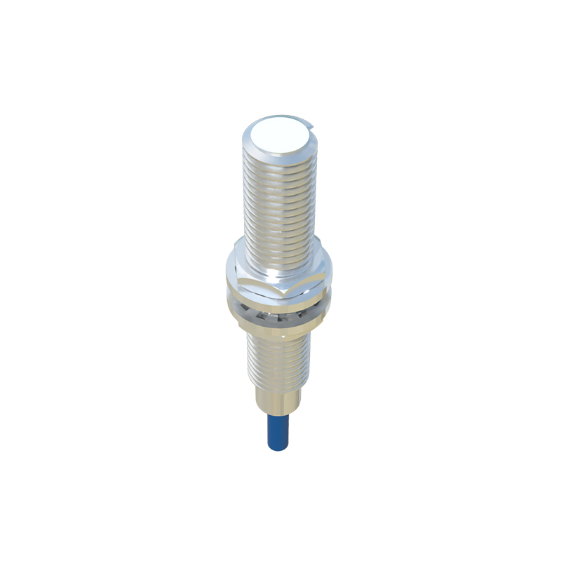
Electrical Issues: The Primary Suspects
The first step in any troubleshooting procedure is to verify the electrical connections and power supply.
1. Incorrect Wiring or Loose Connections: This is the most frequent cause of failure. Always consult the sensor's datasheet. For a 3-wire DC sensor, ensure the brown wire (typically +V) is connected to the positive supply, the blue wire (typically 0V) to negative, and the black wire (output) to the load. For PNP (sourcing) and NPN (sinking) types, the output connection differs fundamentally. Reversing polarity or connecting the load incorrectly can instantly damage the sensor. Check for loose terminals, corroded contacts, or broken wires in the cable or conduit.
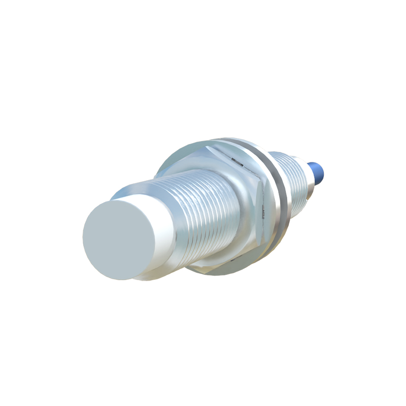
2. Power Supply Problems: Verify that the supply voltage is within the sensor's specified range (e.g., 10-30 VDC). Voltage spikes, surges, or excessive electrical noise (EMI/RFI) from nearby motors, drives, or welding equipment can disrupt or damage the sensor's internal circuitry. Use a multimeter to check for stable voltage at the sensor terminals under load. Consider installing a dedicated, regulated power supply or protective devices like surge suppressors.
3. Load Compatibility: The sensor's output is designed to switch a specific load, usually defined by its maximum current (e.g., 200mA). Connecting a load that exceeds this rating, or one with high inrush current (like a solenoid valve coil), can damage the output transistor. Ensure the load's current draw is within limits. For inductive loads, a flyback diode or RC snubber across the load is often necessary to protect the sensor from voltage transients generated when the load is switched off.
Mechanical and Environmental Factors
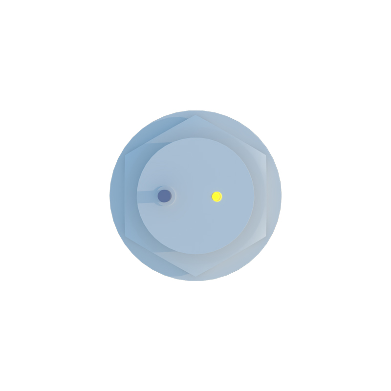
The operating environment can severely impact sensor performance and longevity.
1. Physical Damage and Misalignment: Inspect the sensor housing for cracks, dents, or signs of impact. The sensing face must be clean and unobstructed. Even a thin layer of metal shavings, grease, or paint can reduce the effective sensing distance. Ensure the target approaches the sensor correctly, within its specified sensing axis. Misalignment can cause the target to be undetected or only intermittently detected.
2. Incorrect Sensing Distance: Do not operate the sensor at its nominal sensing distance (Sn). Always account for derating factors such as supply voltage variations, temperature fluctuations, and target material/size. Industrial standards specify a "usable sensing distance" (Su), which is typically 70-80% of Sn, to ensure reliable operation. A sensor placed too far from its target will not actuate.
3. Environmental Contaminants: Oil, coolant, dust, and conductive chips can coat the sensor, causing malfunction. Select a sensor with an appropriate IP (Ingress Protection) rating (e.g., IP67 for washdown environments). For applications with heavy metallic dust, consider a "flush-mountable" model designed to prevent material buildup on the sensing face.
4. Temperature Extremes: Operating outside the specified temperature range can cause the oscillator circuit (the core of an inductive sensor) to drift or fail. High temperatures can degrade electronic components, while extreme cold can affect plastic housings and seals.
Sensor Selection and Configuration Errors
Sometimes, the sensor itself is not at fault; it was simply the wrong choice for the application.
1. Target Material and Size: Standard inductive proximity sensors detect ferrous metals (like steel) best. For non-ferrous metals (aluminum, copper), the sensing distance is drastically reduced, requiring a sensor specifically designed for such materials. The target must also be large enough and thick enough to interact with the sensor's electromagnetic field. A rule of thumb is that the target should be at least equal to the sensor's face diameter or the square of its sensing distance.
2. Sensor Type Mismatch: Using an inductive sensor to detect a plastic object will not