Proximity sensor switches are fascinating and highly useful components in electronics, capable of detecting the presence or absence of an object without physical contact. Building your own can be a rewarding project that deepens your understanding of sensing technology. This guide provides a practical, hands-on approach to creating a basic inductive proximity sensor switch, commonly used for detecting metallic objects.
Before starting, gather the necessary components. You will need a coil of enameled copper wire (approximately 22-24 AWG), a ferrite core or a large nail to increase sensitivity, a 10k ohm resistor, a 100nF capacitor, a standard NPN transistor like the 2N2222, an LED for visual indication, a 9V battery with a connector, a breadboard for prototyping, and jumper wires. A multimeter is also essential for testing.
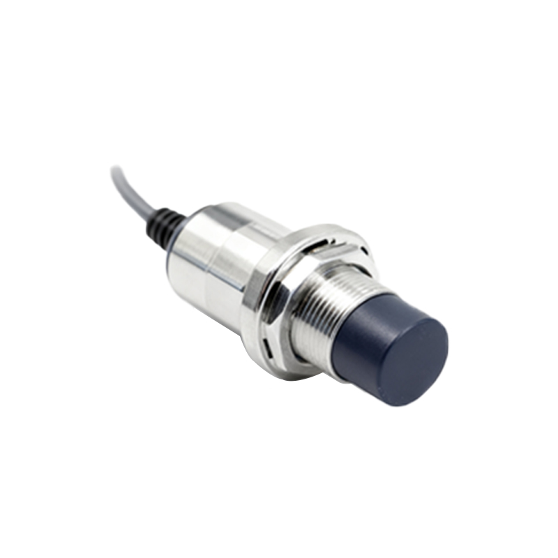
The core principle behind this inductive sensor is electromagnetic induction. The coil generates a high-frequency oscillating magnetic field. When a metallic object enters this field, eddy currents are induced in the metal, which dampens the oscillation. This change is detected by the circuit, triggering the transistor to switch the LED on or off.
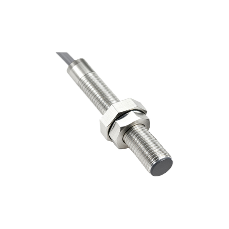
Begin by constructing the sensor coil. Wind the enameled copper wire tightly around the ferrite core or nail. Aim for 50 to 100 turns. Leave about 10 centimeters of wire free at both ends. Once wound, use fine sandpaper to carefully remove the enamel insulation from the very tips of these wire leads to ensure good electrical contact. This coil is the heart of your sensor.
Next, set up the circuit on the breadboard. The configuration is a simple transistor-based oscillator and detector. First, insert the NPN transistor into the breadboard. Connect one lead of your sensor coil to the base of the transistor through the 10k ohm resistor. Connect the other coil lead to the transistor's collector. Now, place the 100nF capacitor between the transistor's base and its emitter. The emitter pin should be connected directly to the negative rail (ground) of the breadboard.
For the output indication, connect the anode (longer leg) of the LED to the positive power rail through a 220-ohm current-limiting resistor. Connect the cathode (shorter leg) of the LED to the collector of the transistor. Finally, connect the positive terminal of your 9V battery to the positive rail of the breadboard and the negative terminal to the ground rail. Double-check all connections against a circuit diagram to avoid errors.
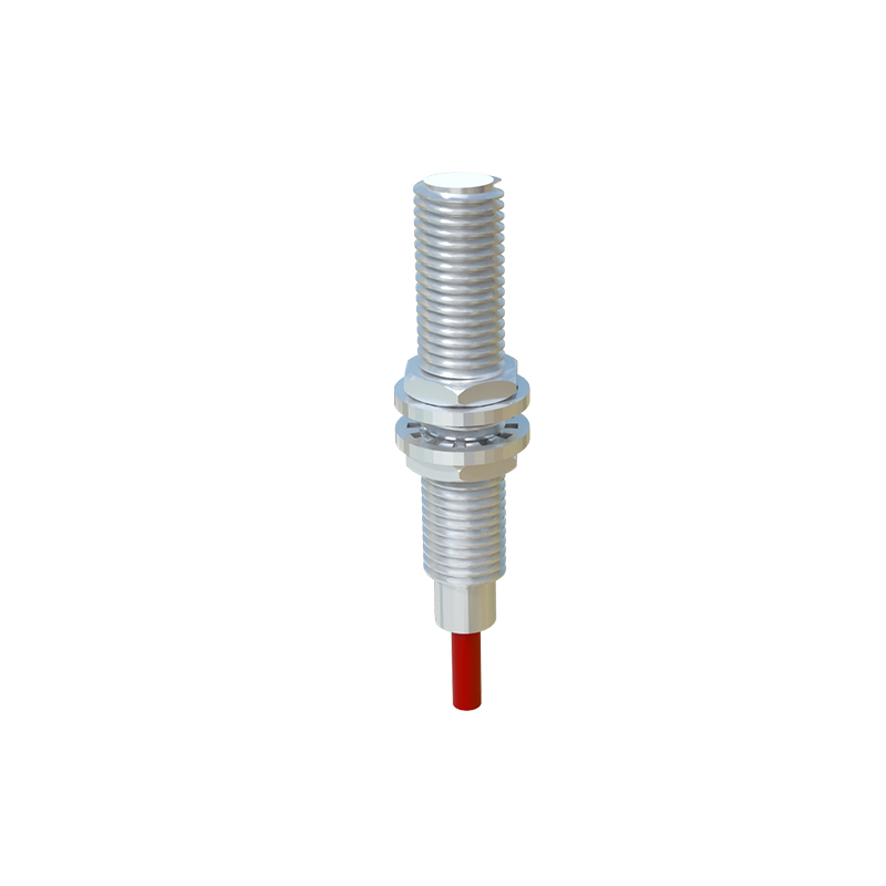
Power on the circuit. Initially, the LED might be off. Bring a metal object, like a screwdriver or a coin, close to the tip of your wound coil. You should observe the LED turning on or off, depending on your specific wiring and transistor state. The detection range will be limited, typically a few millimeters, which is normal for a simple homemade design. If the LED does not respond, first verify all connections. Use the multimeter to check for continuity and ensure the battery voltage is sufficient. The problem often lies in a poor coil connection or an incorrectly oriented transistor or LED.
Once the basic functionality is confirmed, you can experiment. Try increasing the number of coil turns to improve sensitivity. You can replace the LED with a relay module to control higher-power devices like lamps or motors, effectively creating a proximity-activated switch. For more stable operation, consider building the circuit on a perforated PCB and soldering the components. Enclosing the coil and circuit in a small plastic housing will protect it and make it more durable for practical applications.
Understanding the limitations is key. This DIY inductive sensor primarily detects ferrous metals. For non-metallic objects, a capacitive sensing principle would be required, involving different components like a 555 timer IC. Environmental factors like other metal surfaces nearby can interfere with performance. Always ensure proper insulation, especially on the coil, to prevent short circuits.
Building a proximity sensor from scratch demystifies a technology found in countless industrial, automotive, and consumer applications. It reinforces fundamental concepts in electromagnetism and analog electronics. With this working prototype, you have a foundation for more advanced projects, such as object counters, touchless switches, or simple security systems. Remember to disconnect the battery when not in use and handle all electronic components with care to prevent static damage.