Laser sensors have become indispensable tools in modern industrial measurement and automation systems, particularly for precise angle detection. The underlying principle of angle measurement using laser sensors revolves around triangulation, time-of-flight (ToF), or interferometric methods, with triangulation being the most common in industrial applications. This article delves into the schematic principles of laser-based angle measurement, focusing on the triangulation method, its components, and operational workflow.
At the core of a laser angle measurement system is a laser diode that emits a coherent, focused beam of light. This beam is directed onto the target surface whose angle is to be measured. The key components in a typical schematic include: the laser source, a position-sensitive detector (PSD) or a charge-coupled device (CCD) camera, optical lenses, and signal processing electronics. In a standard triangulation setup, the laser beam strikes the target at a known incident angle. The reflected or scattered light from the surface is then collected by a receiver lens and focused onto the PSD or CCD array. The position where the light spot impinges on the detector changes linearly with the target's angular orientation.
The schematic operation can be broken down into distinct stages. First, the laser emitter projects a stable beam onto the measurement point. If the target surface is perfectly perpendicular to the beam, the reflected spot will hit the center of the detector. However, any angular deviation—tilting of the surface—causes a displacement of the reflected spot on the detector plane. This displacement is captured by the PSD, which generates electrical signals proportional to the spot's position. These analog signals are then converted into digital data via an analog-to-digital converter (ADC). The central processing unit (CPU) or a dedicated microcontroller uses pre-calibrated algorithms to compute the angle based on the known geometry: the baseline distance between the laser emitter and the detector, the incident angle, and the detected spot displacement.
Mathematically, the angle θ can be derived from the triangulation formula: θ = arctan(d / L), where d is the displacement on the detector and L is the baseline distance. Advanced systems incorporate multiple laser beams or array detectors to measure complex angles or compensate for surface irregularities. For instance, some high-precision sensors use dual-laser triangulation, where two beams project onto the target, and the system calculates the angle from the differential displacement of both spots, enhancing accuracy and reducing errors from vibration or surface texture.
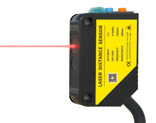
Environmental factors such as ambient light, dust, or surface reflectivity can affect measurement accuracy. Therefore, modern laser sensor schematics often include filtering techniques—like modulated laser pulses and synchronous detection—to mitigate noise. Additionally, temperature compensation circuits are integrated to maintain stability across operating conditions. In applications like robotic arm alignment, automotive assembly, or structural monitoring, these sensors provide real-time, non-contact angle data with resolutions down to arc-seconds.
The evolution of laser angle measurement schematics continues with the integration of MEMS (Micro-Electro-Mechanical Systems) and smart sensor technologies, enabling compact, low-power designs with embedded communication protocols (e.g., IO-Link, Ethernet/IP). Understanding these schematic principles is crucial for engineers to select, calibrate, and deploy laser sensors effectively, ensuring reliable performance in precision-driven industries.