In the realm of industrial automation and control systems, proximity sensors are indispensable components for detecting the presence or absence of objects without physical contact. A critical, yet often overlooked, aspect of selecting the right sensor is determining its appropriate power rating. This parameter is not merely a number on a datasheet; it is fundamental to ensuring reliable operation, longevity, and system safety. This article delves into the factors influencing power requirements and provides a framework for selecting the optimal power rating for your application.
First, it is essential to understand what "power rating" entails for a proximity sensor. Typically, this refers to its electrical consumption and the voltage/current ranges it can operate within. Most industrial proximity sensors are low-power devices, designed to interface with Programmable Logic Controllers (PLCs) and other control systems. They are commonly available in DC versions (e.g., 10-30V DC) and AC versions (e.g., 90-250V AC). The power consumption is usually specified in milliamps (mA) or watts (W).
The primary factor dictating the power requirement is the sensor's operating voltage. A sensor designed for a 24V DC system will have a different current draw and, consequently, a different power rating than one designed for 120V AC. The fundamental formula, Power (P) = Voltage (V) x Current (I), governs this relationship. Therefore, a sensor's datasheet will specify its nominal voltage and its maximum current consumption.
However, the "right" power is not solely about matching the supply voltage. Several application-specific factors must be considered:
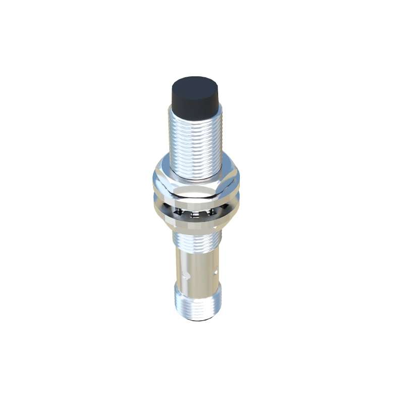
1. Load Compatibility: The sensor's output stage (typically PNP or NPN for DC sensors) must be compatible with the input module of the PLC or relay it is driving. The sensor's output current rating must be sufficient to drive the connected load. Exceeding the maximum current can damage the sensor, while insufficient current may fail to activate the load reliably. Always check the load's input impedance or required operating current.
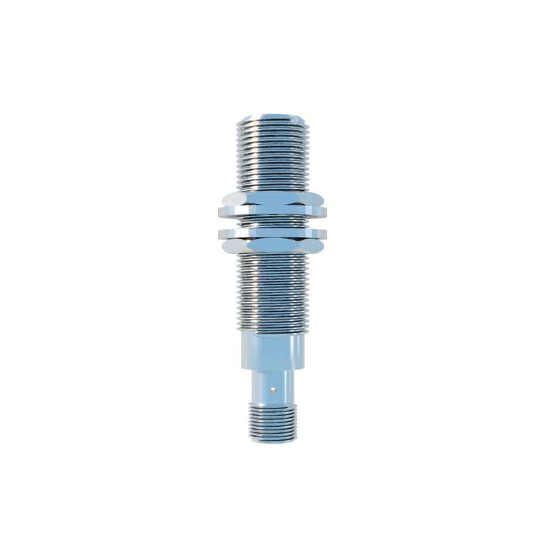
2. Wiring Distance and Voltage Drop: In large installations, sensors may be located far from the power supply. Long cable runs introduce resistance, leading to a voltage drop at the sensor. A sensor operating at the lower limit of its voltage range (e.g., 10V for a 10-30V DC sensor) might malfunction if the voltage drops further. Selecting a sensor with a wider operating voltage range or calculating the required wire gauge to minimize voltage drop is crucial. This indirectly affects the effective power delivered to the sensor.
3. Duty Cycle and Environmental Conditions: While many proximity sensors are rated for continuous operation, high ambient temperatures can derate their performance. In such environments, ensuring the sensor is not operating at the absolute upper limit of its current/power specification enhances reliability and prevents thermal overload.
4. Inrush Current: Some sensors, particularly AC-powered models or those with specific protection circuits, may have a high inrush current at switch-on. This momentary surge, though brief, must be accounted for in the power supply's capacity and any upstream fusing. A power supply that is only rated for the steady-state current may fail or cause a voltage sag affecting other devices.
5. Number of Sensors on a Single Power Supply: A common practice is to power multiple sensors from a single DC power supply. The total current draw of all sensors, plus a safety margin (typically 20-30%), must not exceed the power supply's rated current output. This aggregate calculation is vital for preventing overload.
As a practical guideline, for standard DC inductive or capacitive proximity sensors in benign environments, the power selection is often straightforward: choose a sensor matching your control system's voltage (e.g., 24V DC is an industry standard) and ensure its current draw is within the capacity of your power supply and output module. For example, a typical 18mm cylindrical inductive sensor might draw less than 200mA. The key is to always consult the manufacturer's datasheet for the exact specifications under your intended operating conditions.
For more demanding applications—such as high-speed counting, use in extreme temperatures, or with very long cables—a more detailed analysis is warranted. Consider sensors with features like short-circuit protection, surge immunity, and extended voltage ranges. In these cases, the "right" power rating is one that provides a buffer against real-world variances in supply voltage and load conditions.
In conclusion, determining the suitable power for a proximity sensor is a systems-level task. It requires moving beyond simple voltage matching to a holistic view of the electrical network, including the power supply, wiring, load, and environmental stressors. By carefully evaluating the current consumption, voltage drop, and aggregate load, engineers can ensure their proximity sensors operate with the efficiency and robustness required for modern industrial automation, thereby minimizing