Proximity sensors are vital components in industrial automation, machinery, and safety systems. Among the various types, 4-wire sensors are popular for their versatility, offering both Normally Open (NO) and Normally Closed (NC) output signals from a single device. Correct wiring is crucial for reliable operation and safety. This guide provides clear, practical instructions on how to properly connect a 4-wire DC proximity sensor.
First, it's essential to understand the function of each wire. A standard 4-wire DC proximity sensor typically has the following connections:
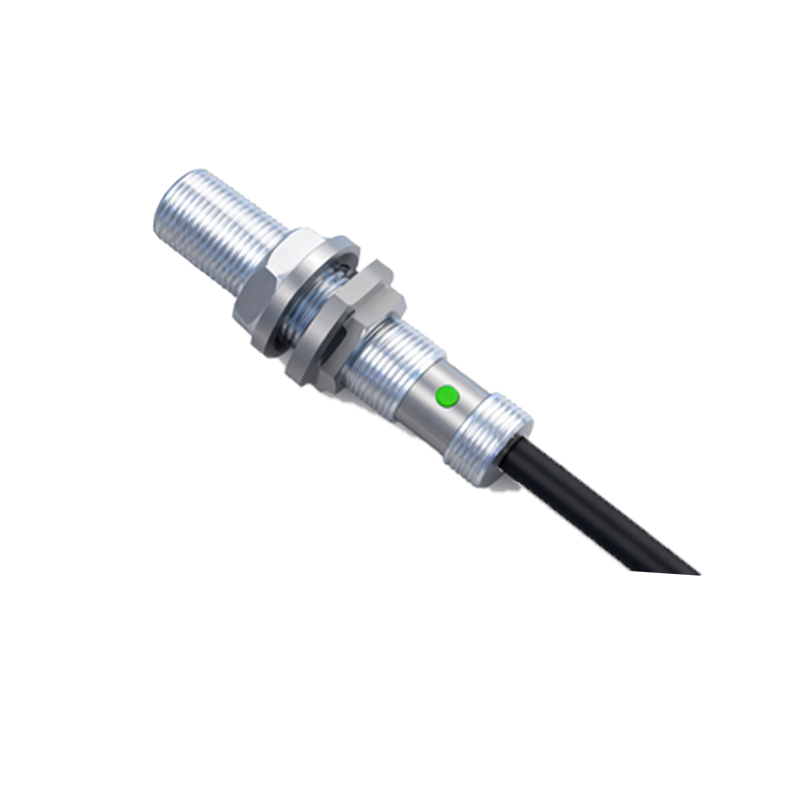
Brown Wire: This is the positive supply voltage wire (+V). It must be connected to the positive terminal of your DC power source.
Blue Wire: This is the negative or common wire (0V). It must be connected to the negative terminal of your DC power source.
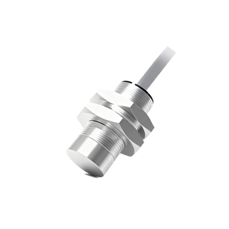
Black Wire: This is the output signal wire for the Normally Open (NO) contact. When a target is detected, this circuit closes, and voltage appears on the black wire.
White Wire: This is the output signal wire for the Normally Closed (NC) contact. When a target is detected, this circuit opens, and voltage is removed from the white wire. Often, the white wire may be paired with the black wire in a complementary fashion.
Important Pre-Wiring Steps:
1. Identify Your Sensor: Always consult the sensor's datasheet or the label on its housing. Confirm it is a DC sensor (typically 10-30V DC) and note the exact voltage rating.
2. Identify Your Load: Determine what the sensor will control—a Programmable Logic Controller (PLC) input, a relay coil, an indicator lamp, etc. Note its voltage and current requirements.
3. Power Off: Ensure all power to the circuit is disconnected and locked out/tagged out (LOTO) before handling any wires.
4. Prepare Tools: You will typically need wire strippers, screwdrivers, and possibly a multimeter for verification.
Standard Wiring Procedure:
Step 1: Connect the Power Wires.
Connect the brown wire to the positive (+) side of your DC power supply. Connect the blue wire to the negative (-) or 0V side of the same power supply. This provides the operating voltage for the sensor's internal electronics. Incorrect polarity can damage the sensor.
Step 2: Connect the Output Wire (Choose NO or NC).
You will use either the black (NO) or white (NC) wire, depending on your application's logic.
For a Normally Open (NO) Configuration: Connect the black wire to one terminal of your load (e.g., the PLC input terminal). Connect the other terminal of your load back to the negative side (-) of the power supply. In this setup, when no target is present, the circuit is open and no signal flows. When a target is detected, the sensor closes the circuit between brown (via internal electronics) and black, sending a signal to the load.
For a Normally Closed (NC) Configuration: Connect the white wire to your load, and connect the other side of the load back to the positive side (+) of the power supply. In this setup, a signal is continuously present when no target is near. When a target is detected, the sensor opens this circuit, breaking the signal.
Step 3: Insulate and Secure.
Ensure all connections are tight and secure. Use appropriate terminal blocks or connectors. Keep wires neatly routed and away from sources of electrical noise or physical damage.
Verification and Testing:
1. After wiring, double-check all connections against the diagram.
2. Restore power cautiously.
3. Use a multimeter to test. For an NO output (black wire), measure voltage between the black wire and the blue wire. It should read near 0V without a target, and near the supply voltage (e.g., 24V) when a metal target is brought close to the sensing face. The opposite is true for the NC output (white wire).
4. Observe the behavior of your connected load (e.g., a pilot light or PLC input status) to confirm correct operation.
Common Wiring Diagrams:
Sourcing (PNP) vs. Sinking (NPN): Most 4-wire DC sensors are configured as PNP (sourcing), where the output wire (black or white) switches the positive voltage. The wiring described above is for a standard PNP sensor. Always verify if your sensor is PNP or NPN, as the load connection point changes.