In the world of industrial automation and machinery monitoring, the ability to accurately measure rotational or linear speed is paramount. Among the various technologies employed for this critical task, proximity speed sensors stand out for their reliability, non-contact operation, and versatility. Unlike traditional mechanical tachometers or optical encoders that may require physical contact or clear line-of-sight, proximity sensors detect the presence or passage of a target without making direct contact, making them ideal for harsh, dirty, or demanding environments.
The fundamental operating principle of a proximity speed sensor is based on electromagnetic induction or capacitive/inductive effects. The most common type is the inductive proximity sensor used for detecting metallic targets. These sensors contain an oscillator circuit that generates a high-frequency electromagnetic field at the sensing face. When a conductive metal target, such as a gear tooth, keyway, or bolt head, enters this field, eddy currents are induced on the target's surface. This causes a change in the oscillation amplitude within the sensor. An internal circuit detects this change and triggers a solid-state switch, producing a digital output pulse. By counting these pulses over a known period, the rotational speed (RPM) or linear speed can be precisely calculated. For non-metallic targets, capacitive proximity sensors, which detect changes in capacitance, are utilized.
The core components of a typical system include the sensor itself, a ferrous or conductive target (like a gear or a dedicated pulse wheel), and a monitoring device such as a PLC, frequency counter, or dedicated tachometer. The sensor is mounted at a precise gap from the target. As the target rotates or moves, each passing feature generates a distinct pulse. The frequency of this pulse train is directly proportional to the speed. Advanced sensors integrate signal conditioning to provide a clean, square-wave output immune to electrical noise, which is crucial in industrial settings.
The applications for proximity speed sensors are vast and critical across numerous sectors. In automotive manufacturing, they monitor the speed of assembly line conveyors and robotic arms. Within the automotive vehicle itself, they are essential for anti-lock braking systems (ABS), measuring wheel speed to prevent lock-up. In the aerospace industry, they monitor turbine and fan speeds in jet engines, where reliability is non-negotiable. Heavy industries such as mining, steel, and pulp & paper use these sensors on large motors, crushers, rollers, and fans to prevent catastrophic damage from overspeed or underspeed conditions. They are also fundamental in wind turbines for monitoring blade rotation and in packaging machinery to ensure consistent product flow.
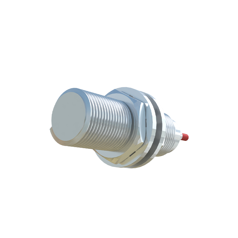
Selecting the right proximity speed sensor requires careful consideration of several parameters. First, the target material dictates the sensor technology: inductive for metals, capacitive for non-metals. The sensing distance, or range, must be suitable for the installation geometry and account for any mechanical tolerances or vibrations. The required output type is also key; most provide a digital PNP or NPN signal, but some offer analog outputs (4-20 mA or 0-10V) proportional to speed. Environmental factors are critical. Sensors are rated with an Ingress Protection (IP) code for dust and water resistance. For high-temperature applications near engines or furnaces, models with extended temperature ranges are necessary. The sensor's housing material, typically nickel-plated brass or stainless steel, must withstand chemical exposure or physical impact. Finally, the electrical specifications, such as supply voltage and current consumption, must match the control system's capabilities.
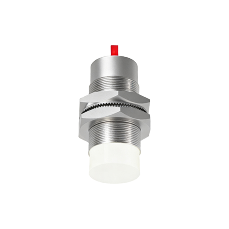
Installation and maintenance are straightforward but vital for optimal performance. Correct mounting is essential to maintain the proper gap between the sensor and the target. This gap must be within the sensor's specified range and should be adjusted to account for any axial or radial runout of the rotating shaft. The sensor should be securely fastened to resist vibration. Wiring should follow best practices, such as using shielded cables and routing them away from high-power lines to minimize electromagnetic interference. While these sensors are largely maintenance-free due to their solid-state design, periodic checks are recommended. This includes verifying the mounting integrity, cleaning the sensing face of any accumulated debris or metallic dust (which can cause false triggering), and checking the output signal with an oscilloscope or multimeter to ensure pulse integrity.
Compared to other speed sensing methods like optical encoders or Hall-effect sensors, proximity sensors offer distinct advantages. Their rugged, sealed construction allows them to perform in environments with oil, grease, coolant, and dirt that would foul optical sensors. They have no moving parts to wear out, leading to a long service life and high mean time between failures (MTBF). Their non-contact nature eliminates friction and wear on the target. However, they also have limitations. Their accuracy is inherently tied to the consistency of the target features; a damaged gear tooth will cause an error. The sensing range is relatively short compared to some optical methods. Additionally, standard inductive sensors are only effective on metallic targets