Ultrasonic proximity sensors are widely used in industrial automation, robotics, and safety systems due to their reliability and non-contact detection capabilities. Proper calibration and adjustment are essential to ensure accurate performance and longevity. This guide provides a comprehensive overview of the key steps and considerations for tuning ultrasonic sensors effectively.
Understanding the basic working principle is the first step. Ultrasonic sensors emit high-frequency sound waves that bounce off objects and return to the receiver. The time taken for the echo to return is used to calculate distance. Factors like temperature, humidity, and surface material can affect wave propagation, making calibration necessary for precision applications.
Begin with installation checks. Ensure the sensor is mounted securely, aligned correctly, and free from obstructions in its detection path. Vibrations or misalignment can lead to false readings. The sensing face should be clean, as dust or debris can dampen ultrasonic waves.
Most modern ultrasonic sensors feature adjustable parameters via built-in potentiometers, digital interfaces, or software tools. Key settings include sensing range, response time, and output configuration. To adjust the sensing range, identify the minimum and maximum detection limits specified in the datasheet. Use a test object at a known distance to fine-tune the threshold. Rotate the range potentiometer clockwise to increase sensitivity or counterclockwise to decrease it. For sensors with teach-in functions, follow the manufacturer’s instructions to program limits by placing the object at desired points.
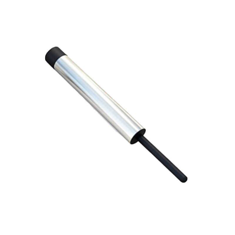
Response time adjustment balances speed and stability. In dynamic environments, a faster response may be needed, but it can increase susceptibility to noise. Slower settings smooth out fluctuations but may delay detection. Adjust this based on application requirements—for example, use faster responses for high-speed assembly lines and slower ones for stationary measurements.
Temperature compensation is critical. Ultrasonic wave speed changes with air temperature, leading to drift. Many sensors include automatic temperature compensation (ATC). If unavailable, manual recalibration when environmental conditions shift is advised. Some advanced models allow input of temperature data via external probes.
Output configuration involves setting switch points, hysteresis, and output type (e.g., analog, digital, or IO-Link). Hysteresis prevents output chattering near threshold boundaries by creating a dead band. Adjust it to avoid rapid toggling when an object hovers at the detection edge. Verify outputs with a multimeter or PLC to ensure signals match intended actions.
Testing and validation are crucial. After adjustments, perform tests with various objects, materials, and distances. Document settings for future reference. Regular maintenance, including periodic recalibration and cleaning, sustains accuracy over time.
Common issues include false triggers from acoustic interference, inconsistent readings due to surface angles, or reduced range from environmental factors. Troubleshoot by isolating noise sources, adjusting sensitivity, or adding shielding. Consult the sensor’s manual for error codes and diagnostics.
In summary, meticulous calibration tailors ultrasonic sensors to specific applications, enhancing reliability. Always prioritize safety by verifying sensor operation before deployment in critical systems. With proper adjustment, these sensors deliver robust, long-lasting performance across diverse industries.